T M 5 - 6 1 1 5 - 5 8 4 - 12
N A V F A C P - 8 - 6 2 2 - 12
T O - 3 5 C 2 - 3 - 4 5 6 - 1
TM-05682C-12
On ASK equppied
4-31. LOW OIL PRESSURE SWITCH.
generators, remove oil access door.
a. Test on Equipment (see figure 4-30). Disconnect
leads from terminals 1 and 2. With master switch in off
position, use ohmmeter to check for continuity between
terminals 1 and 2 of switch. If continuity is indicated,
replace switch. Connect leads to switch terminals 1 and
2.
b. Removal. Disconnect leads from terminals 1 and 2.
Use wrench on square portion at base of switch (11) and
remove from adapter (5).
c. Bench Test. Connect switch to a controllable supp-
ly of dry compressed air. Connect ohmmeter across ter-
minals 1 and 2 and slowly apply compressed air. Switch
should close (continuity) when 14 ± 2 psi of compressed
air is applied.
4-34
Change 7
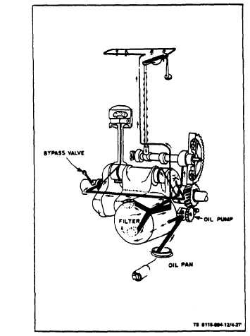
Figure 4-27. Pressure Oil System
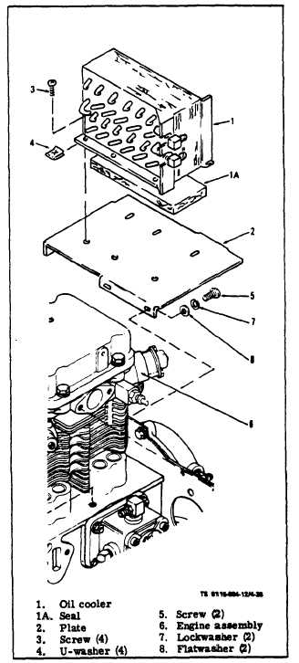
Figure 4-28. Oil Cooler Assembly