TM 5-6115-584-12
NAVPAC P-8-622-12
TO-35C2-3-456-1
TM-05682C-12
(20) and spring (12). Slide gear (5) out through
opening in engine back plate. Clean any gasket (13)
material from switch and back plate.
d. Repair. Repair starter lockout switch by re-
placing parts found to be defective under inspection
e. Replace. Make certain spacer (16) is on shaft
and slip timing gear (5) through opening in engine
back plate. Make certain that shaft seats properly in
gear cover and that gear teeth are properly meshed.
Place thrust plunger (20) and spring (12) in gear
shaft. Slide switch and gasket (13) over shaft and
attach to engine back plate with two screws (9) and
Iockwashers (10). Use a new gasket (13) between
switch and engine back plate. Reconnect electrical
connector (8).
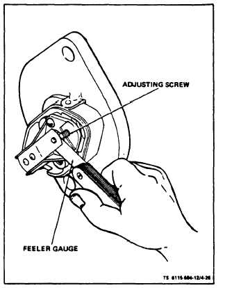
f. Adjust. With engine stopped, remove cover re-
taining wing nut (1) and remove cover (3). Turn
adjusting screw (14) clockwise until points open.
Turn adjusting screw counterclockwise until points
just ClOSe (see figure 4-26). Start engine and dis-
connect switch from wiring harness at connector (8,
figure 4-25). Adjust adjusting screw for a 0.040 point
gap. Replace cover (3) and wing nut (1). Reconnect
connector (8).
Be sure two wires are recessed in slot of
housing before tightening cover down.
Section XI.
4-29. FUNCTION AND DESCRIPTION
The diesel engine has pressure Iubrication to all
working parts (see figure 4-27). The oil system
includes oil intake cup, gear type oil pump, bypass
valve, oil pressure gauge, low oil pressure shutoff,
full-flow oil filter, oil coder, and passages to de-
liver oil throughout the engine. Oil is held in the oil
base, and forced through the oil filter and oil cooler
by the pump. Lines leading to the rocker housing,
passages through the block to crankshaft and front
camshaft bearing, crankshaft passages to connecting
rod bearings and connecting rod passages to piston
pin bushings complete the oil system network The
bypass valve controls oil pressure by allowtng excess
oil to flow directly back to the crankcase.
4-30. OIL COOLER
a. Inspect (see figure 4-28). On ASK equipped generators,
remove ASK cover assembly (para 5-3). Inspect oil cooler (1)
for physical damage. Visually check for leaks where oil cooler
is connected to oil hoses (figure 4-29). Check that cooler Is
securely fastened to mounting plate (2, figure 4-28) and that
plate is securely fastened to engine. Inspect all hoses for
Figure 4-26. Adjusting Starter Lockout Switch
MAINTENANCE OF OIL SYSTEM
leaks and physical damage. Inspect seal (1A, figure 4-28)
and replace if damaged. Blower housing must be removed
to inspect cooler and hoses.
b. Service. Every 500 operating hours clean oil
cooler fins with air gun (50 psi) held 12 inches away
from the fins. Every 2500 operating hours remove
oil cooler and flush in both directions using solvent
at 25 psi.
c. Remove. Remove blower housing. Disconnect oil
cooler hoses at valve of oil filter adapter (see figure
4-29), Drain cooler into suitable container. Remove
four machine screws (3, figure 4-26) and special U-
shaped washers (4) attaching oil cooler (1) and oil
cooler seal (1A) to mounting plate (2) and remove
cooler (1).
Remove and check hoses. Plug hose
if not used immediately.
d. Replace. Install oil cooler (1) and oil cooler seal (1A) on
mounting plate (2) and secure with screws (3) and special
U-shaped washers (4), Attach oil hoses to cooler as shown in
figure 4-29. Replace blower housing shown in figure 4-29.
Replace blower housing, Replace any oil lost. On ASK equipped
generators, replace ASK cover assembly (para 5-3).
Change 7
4-33