TM 5-6115-584-12
NAVFAC P-8-622-12
TO-35C2-3-456-1
TM-05682C-12
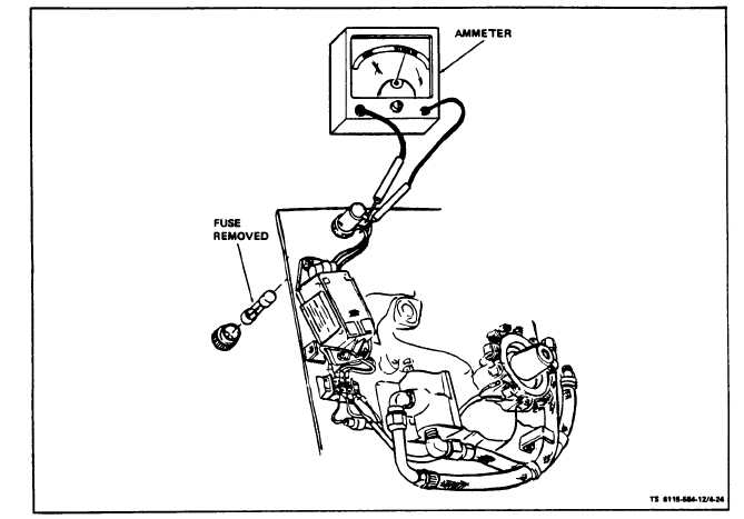
Figure 4-24. Testing Battery Charging Regulator/Rectifier Assembly
(3) Remove (see figure 4-23). Disconnect and tag
(1) Inspect. Inspect terminal block (3) for physi-
leads on regulator/rectifier assembly. Remove screws
(7), washers (8) and nuts (6) attaching assembly to
engine back plate and remove assembly.
(4) Replace. Attach assembly to engine back plate
with three screws (7), six lockwashers (8), and three
nuts (6). Attach tagged leads from assembly.
c. Battery Charger Circuit Fuse (see figure 4-23).
(1) Inspect. Inspect fuse (9) for physical damage.
Check that end caps on fuse are free of corrosion.
Check that fuse is properly mounted in fuse holder.
(2) Test. Test fuse (9) for continuity using an
ohmmeter. Replace fuse that does not show con-
tinuity.
(3) Replace. Remove fuse holder cap and remove
fuse. Install new fuse in fuse holder body and attach
fuse holder cap.
d. Terminal Block (see figure 4-23).
cal damage. Check that electrical connections to block
are clean and tight. Check that block is securely
fastened to engine back plate (4).
(2) Test. Tag and disconnect leads to terminal
block. Check to see that there is no continuity be-
tween terminals on terminal block and ground.
(3) Replace. Tag and disconnect leads at terminal block.
Remove two screws and nuts attaching block to engine plate and
remove block. Attach new terminal block to engine back plate with
two screws and nuts. Connect previously tagged leads to terminal
block. Remove tags. On ASK equipped generators, install ASK
cover assembly (para 5-3).
4-28. STARTER LOCKOUT SWITCH AND GEAR
ASSEMBLY.
On ASK equipped generators, remove oil access door.
a. Inspect (see figure 4-25). Disconnect negative
battery cable. Remove wing nut (1) and cover (3) and
inspect switch contact points between contact spring (15)
and adjusting screw (14) for physical damage.
b. Test. With engine off, disconnect switch at
connector (8). Using an ohmmeter, test that there is
Change 7 4-31


