TM 5-6115-584-12
NAVFAC P-8-622-12
TO-35C2-3-456-1
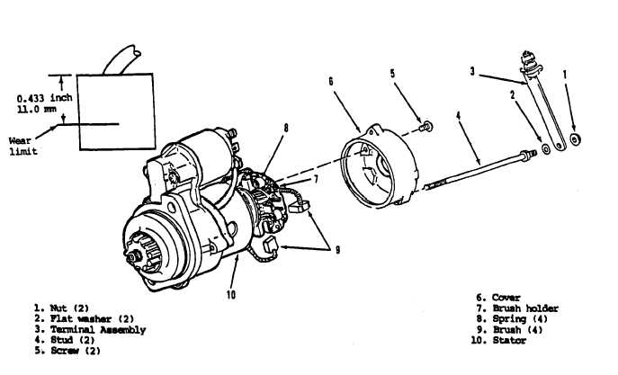
Figure 4–21 A. Inspecting Starter Brushes, Style II Starter
(2) Install Solenoid. Refer to figure 4-22.
Place solenoid (1) on frame (8) and move to rear until
field terminal (11) enters field coil lead strap. Install nut
and Iockwasher, do not tighten. Install screws (14), do
not tighten. Align the plunger (3) on yoke (6) and insert
clevis pin (5) and secure with cotter pin (4). Install lead
(12) on small solenoid terminal and on negative termi-
nal (9) Secure with nuts and Iockwashers. Tighten nut
and Iockwasher on field terminal (11), and screws (14)
f. Repair. Style II Starter.
(1) Remove Solenoid. If solenoid is defec-
tive, remove as follows:
Refer to figure 4–22A.
Remove nut and Iockwasher on terminal (M) freeing
lead (L). Remove screws (1), solenoid switch (3) and
Spacers (2). Retain hardware from terminal (M).
NOTE
Solenoid mounting screw removal
may require the use of an impact type
driver.
(2) Install Solenoid. Refer to figure 4-22A.
Support new solenoid (3) and original spacer(s), en-
gage solenoid plunger on Iever(yoke), secure using
new screws (1).
g. Install Starter.
Refer to figure 4–18. Slide
starter into opening in flywheel housing (17). Make
certain starter lies flat against housing, Attach starter
to housing with screws (13) and Iockwashers (14). For
Style I Starter, swing support bracket (12) into position
at back of the starter, and attach with screw (9), nut (7)
and Iockwasher (8). Tighten screw (1 0) and lock
washer (11) securing support bracket (12) to engine
block. Replace tagged leads per diagram, figure 4-18.
Remove tags.
4–27. BATTERY CHARGING ALTERNATOR.
a. Battery Alternator Stator (see figure 4-23).
On ASK equipped generators; remove ASK cover as-
sembly (para 5-3).
(1) Remove blower housing (see paragraph
4-17).
(2) Inspect. The presence of the blower
wheel limits inspection of the battery alternator to in-
specting that two leads (1) from stator (2) are free of
damage and are not rubbing against blower wheel and
are securely connected to terminal block (3) located on
engine back plate (4).
Change 10
4-28.3


