TM 5-6115-584-12
NAVFAC P-8-622-12
TO-35C2-3-456-1
NOTE
Always detach negative (–) cable first
and reattach it last.
b. Battery Top (Hold–down) Frame (see figure
3-23).
(1) Remove. Tag and disconnect battery ca-
bles (10) and jumper cable (11 ) from batteries (1).
Remove six nuts (4) and flatwashers (5) holding top
frame (2) in place, and remove top frame. If hook bolts
(3) do not need replacing, they need not be removed
from frame (6).
(2) Replace. Hook six bolts (3) onto bottom
frame (6). Place top frame (2) over batteries (1) mak-
ing certain hook bolts slide through the top frame.
Secure top frame in place with six flatwashers (5) and
nuts (4). Reattach battery cables (10) and jumper ca-
ble (11).
(3) Repair. Straighten battery top frames
making certain they fit securely over batteries and hold
batteries in place.
c. Storage Batteries.
Battery electrolyte can cause severe
burns to the skin. Always flush ex-
posed parts of the skin with water as
quickly as possible.
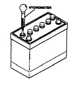
(1) Test. Charge battery for a sufficient time
for battery to be fully charged (1 to 2 hours). Test each
cell of battery separately using a hydrometer. Remove
cap from one cell and draw fluid from that cell into hy-
drometer. Hydrometer must register a specific gravity
of 1.260 to 1.280. If specific gravity is below 1.260,
charge battery. See figure 4–17. Replace fIuid into cell
and replace cap. Check each battery cell using this
procedure. If one or more cells in a battery will not take
a charge, replace battery.
(2) Remove. Remove battery cables and top
frames, a and b above. Remove batteries from battery
frame.
(3) Replace. Place batteries in battery frame
with negative (-) terminals toward control panel end of
generator and positive (+) terminals toward blower
housing end of generator. Install battery top frame and
battery cables as outlined above.
Figure 4–17. Testing Batteries
4-26. ENGINE STARTER ASSEMBLY,
a. Test. On equipment (see figure 4–1 9). On
ASK equipped generators, remove BATTERIES ac-
cess door.
(1) Make sure batteries are fully charged and
that all battery and starter cables are serviceable and
properly installed. Disconnect all starter to solenoid
connection.
(2) Connect voltmeter as shown in figure
4–19, Test a. If voltage is indicated, solenoid is defec-
tive. Proceed to step (4).
(3) Reconnect all starter to solenoid connec-
tions. Connect voltmeter as shown in figure 4–19, Test
a. If battery voltage (24 volts) is not indicated, the
starter (B1 ) may be defective. Proceed to step (4).
(4) Momentarily connect a jumper as shown
in figure 4–19, Test b. Voltmeter reading should drop
to zero and starter should crank engine. If voltmeter
reading does not drop to zero, solenoid is defective. If
voltmeter readings drop to zero but starter fails to crank
engine, starter is defective.
b. Removal (see figure 4-18). On ASK genera-
tors remove batteries access door.
Tag and
disconnect leads (1) thru (6). On Style I Starters, re-
move nut (7), Iockwasher (8), screw (9). Loosen but do
not remove screw (1 0), Iockwasher (11) and swing
4-26
Change 10