TM 5-6115-584-12
NAVFAC P-8-622-12
TO-35C2-3-456-1
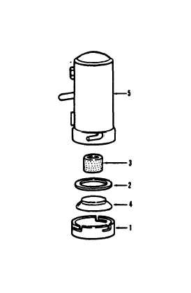
1. Cover
2. Gasket
3. Strainer
4. Magnet
5. Fuel pump
TS
6115-58412/4-13
Figure 4-13. Fuel Pump
(2) Check for continuity between terminals of the
fuel shut-off solenoid. If continuity is not obtained, the
unit is unserviceable.
(3) Check for ground between fuel shut-off solenoid
terminals and ground. If terminals are grounded, the
unit is unserviceable.
(4) Connect the solenoid into test set-up (fig 4-15).
(5) With switch (S1) closed, the plunger should ac-
tuate and the currant draw should be 0.25 ampere dc.
(6) If plunger does not actuate or, if meter reads
above 0.35 ampere, replace solenoid.
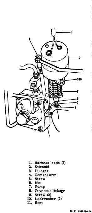
c. Remove (see figure 4-14). Tag and disconnect
harness leads (1). Remove the shut-off solenoid by
removing screws (9) and lockwashers (10).
d. Installation. Mount shut-off solenoid using screws
(9) and lockwashers (10). Reconnect previously tagged
and removed harness wires (1).
e. Adjust. The solenoid plunger (3) should be adjusted so it
fully stops Injection when In the de-energized position. With
engine running at full rated bad, clearance between plunger (3)
and control arm (4) should be at least 1/8 inch. To adjust the
plunger length, turn the knurled head screw (5) and jam nut (6)
on bottom of plunger. On ASK equipped Generator Sets, install
right panel assembly (para. 5-6).
Figure 4-14. Adjusting Fuel Shut-Off Solenoid
Change 7
4-23