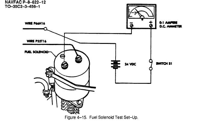
Figure 4-15
NAVFAC P-8-622-12
TO-35C2-3-456-1
TM 5-6115-584-12
Section X. MAINTENANCE OF ENGINE ELECTRICAL SYSTEM
4–24.
DESCRIPTION AND FUNCTION
a. The engine is cranked by a 24 volt electric
starting motor (see figure 1–7). When starting motor
solenoid is energized, the solenoid core pulls in, shift-
ing the pinion gear into engagement with the engine
flywheel ring gear. At the same time, contacts in the
solenoid close to provide a circuit for the starter. The
starting motor is protected from overspeeding by an
overrunning clutch. Two 12 volt batteries in series are
used. The starting switch for this starting circuit is lo-
cated in the control cubicle, A blower wheel alternator
is utilized to maintain the battery charge. The stator is
mounted on the engine block and the permanent mag-
net rotor is mounted into the air cooling system blower.
Solid state diode rectifiers convert the alternating cur-
rent generated in the stator to direct current for battery
charging.
b. Anew (Style II) gear–reduction electric starter
will be installed on engines manufactured during 1990;
and will be available as a replacement when the origi-
nal starter, (Style 1) is no longer available. The Style II
starters are interchangeable with the Style I starter.
4-25. BATTERY ASSEMBLY.
Metal objects making contact be-
tween the positive and negative
battery terminals, or between the
positive battery terminal and the gen-
erator frame can cause FIRE or
EXPLOSION . Always keep the bat-
tery terminal covers on the battery
terminals. See Figure 3-23.
a. Battery Cables (Including Jumper Cable) (see
figure 4–1 6). On ASK equipped generators, remove
BATTERIES access door.
(1) Test. Test battery cable for continuity. Re-
place any cable that does not show continuity.
(2) Remove. Remove negative battery cable
from negative (–) battery terminal. Remove positive
(+) battery cable from positive battery terminal.
Tag and disconnect cables from starter case and
starter solenoid. Remove jumper between batteries.
Clean battery, starter, and starter solenoid terminals
thoroughly and install new cables as given below.
(3) Replace. Attach jumper cable between
negative (–) terminal of one battery and positive (+) ter-
minal of the other battery. Attach positive battery cable
to the “B” Terminal stud on starter solenoid. Attach
negative battery cable (-) to the ground terminal “G” of
the starter. See figure 4-16. Attach positive cable (+)
to positive terminal on one battery and negative cable
(-) to negative terminal on the other battery. Tighten all
terminal connectors securely.
4-24
Change 10


