c. Replacement. See
f i g u r e s
4 - 8
a n d
4 - 9 and
4 - 2 8 . C o n t r o l B o x F u s e a n d L a m p T e s t i n g a n d
pro~eed as follows:
R e p l a c e m e n t .
See f i g u r e 4 - 9 to remove and install control box
(1) Removal. Disconnect two wiring harness
lamps and fuse.
connectors ( 5 9 , f i g . 4 - 7 ) from rear of control box.
Unscrew four capscrews (44) which secure box to
a. Fuse. See
f i g u r e
4 - 9 and remove fuse. Using
mumimeter, check fuse for continuity. If continuity
panel and remove control box (45).
is not obtained, replace fuse.
b.
Lamps.
Press to test each indicator. If an
(2) Installation. Secure control box ( 4 5 , f i g .
ind~cat~s not illuminate, see f i g u r e 4 - 9 and
4 - 7 ) to panel with four capscrews (44). Screw two
~ wiring harness (59) connectors to receptacles at
replace lamp.
Press to test indicator again. E
lamp does not illuminate, replace indicator light
rear of control box (45).
assembly at next higher level of maintenance.
S e c t i o n
I V .
W H E E L
M O U N T I N G
K I T
4 - 2 9 .
G e n e r a l .
a. The wheel mounting kit is provided to enable
the-engine generator set to become mobile. The
wheel mounting kit consists of two detachable wheel-
axle assemblies, parking brake, safety chains,
pintle, and towbar.
The front axle wheels are free
to pivot up to 40 degrees for steering. The mechan-
ical parking brake locks rear wheels against rotation
and is actuated by a hand lever located at the right
rear of the kit.
b. When the wheel mounting kit is installed on the
gen%rator set, the set may be towed a maximum of
5 mph on paved highways. The kit has a ground
clearance of 8 inches and front wheels turn for
steering. For wheel mounting kit operating instruc-
tions, refer to p a r a g r a p h 2 - 2 6 .
4 - 3 0 .
P r e v e n t i v e
M a i n t e n a n c e .
To insure that the wheel mounting kit is ready for
operation at all times, when installed on the genera-
tor set, it must be inspected systematically
so that
defects may be discovered and corrected before they
result @ serious damage or failure. Defects dis-
covered during operation of the kit shall be noted for
future correction, to be made as soon as operation
has ceased. Stop operation immediately if a defici-
ency is noted during operation which would damage
the kit or the end item generator to which it is at-
tached. ml deficiencies and shortcomings SHALL
be record& together with the corrective action on
the applicable form at the earliest possible opportu-
nity. Air Force users shall refer to the applicable
inspection manuals and work card sets in the
T . O . 3 5 C 2 - 3 - Series for periodic preventive main-
tenance requirements and t a b l e 4 - 5 for detailed
procedure.
4 - 3 1 .
T r o u b l e s h o o t i n g .
T a b l e
4 - 6 contains information useful in diagnosing
and correcting unsatisfactory operation of the wheel
mounting kit.
4 - 3 2 .
K i t
M a i n t e n m c e
P r o c e d u r e s .
Inspection, test, service, and repair of the wheel
mounting kit ( f i g u r e s 4 - 1 0 , 4 - 1 1 a n d 4 - 1 2 ) consists of
preventive and corrective maintenance of the various
components of the kit as described in t a b l e 4 - 5 a n d
p a r a g r a p h s
4 - 3 3
t h r o u g h
4 - 3 5 .
4 - 3 3 .
W h e e l s
a n d
T i r e s .
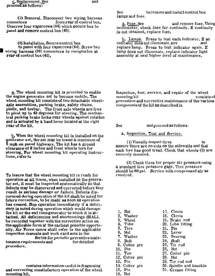
See f i g u r e 4 - 1 0 and proceed as follows:
a. Inspection, Test and Service.
(1) Visually inspect tires ( 5 , f i g . 4 - 1 0 ) to
assure there are no cuts on the sidewalls and that
each tire has good tread. Check that wheels (3) are
securely mounted.
(2) Check tires for proper air pressure using
a standard tire pressure gage. Tire pressure
should be 60 psi.
Service with compressed air as
required,
K E Y t o f i g . 4 - 1 0 .
1.
Nut
2.
Washer
3.
Wheel
4.
Tube
5.
Tire
6.
Nut
7.
Washer
8.
Bolt
9.
Cotter
pin
10.
Pin
11.
Tow
12.
Cotter
pin
13.
Pin
14.
Cotter
pin
15.
Pin
16.
Nut
17.
Clevis
18.
Clevis
19.
Brake
rod
20.
Lube
fitting
21.
Pin
22.
Lever
23.
Bearing
24.
Shaft
25.
Tie
rod
26.
Nut
27.
Cotter
pin
28.
Nut
29. Tie rod end
30. Spindle and knuckle
31. Grease fitting
C h a n g e 1 4 - 2 1