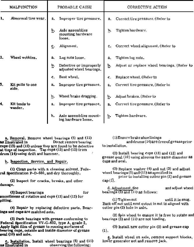
T a b l e
4 - 6 .
W h e e l
M o u n t i n g
K i t
T r o u b l e s h o o t i n g
MALFUNCTION
1.
2.
3.
4.
Abnormal tire wear.
Wheel wobbles.
Kit pulls to one
side.
Kit tends to
wander.
PROBABLE CAUSE
a.
b
—“
c.
—
a.
b
-“
c.
a.
b
—“
a.
b.
Improper tire pressure.
Axle assemblies
mounting hardware
loose,
Alignment.
Lug nuts loose.
Defective or improperly
adjusted wheel bearings.
Bent wheel.
Improper tire pressure.
Wheel brake dragging.
Improper tire pressure.
Axle assemblies mount-
ing hardware loose.
a. Removal. Remove wheel bearings (5) and (11)
as illustrated in f i g u r e 4 - 1 2 . Do not remove bearing
cups (13) and (12) unless they are found to be defective
at ti~e of inspection.
Tap cups (13) and (12) from
drum (14) using drift and hammer.
/
~.
Inspection,
Service,
and
Repair.
(1) Clean parts with a cleaning solvent, Fede-
ral Specification P-D-680, and dry thoroughly.
(2) Inspect for cracks, breaks, and other
damage.
(3) Inspect bearings ( 5 a n d 1 1 , f i g . 4 - 1 2 ) for
smoothness of rotation and cups (13) and (12) for
pitting.
(4) Repair by replacing defective parts. Bear-
ings and cups are matched sets.
(5) Pack bearings with grease conforming to
Federal ~ecification W-G-632, type A, grade 2.
Apply light film of grease to running surfaces of
bearing cups, outside and inside diameter of grease
seal (10) and axle.
c. Installation. Jnstall wheel bearings (5) and (11)
as Illustrated
in f i g u r e 4 - 1 2 observing the following:
CORRECTIVE ACTION
a.
Correct tire pressure. (Refer to
p a r a g r a p h
4 - 3 3 . )
b
Tighten hardware.
—.
c.
a.
b
—.
c.
a.
b
—.
a.
b
—.
Correct wheel alignment. (Refer to
p a r a -
g r a p h
4 - 3 6 . )
Tighten lug nuts.
Adjust or replace wheel bearings. (Refer to
p a r a g r a p h
4 - 3 4 . )
Replace wheel. (Refer to p a r a g r a p h 4 - 3 3 . )
Correct tire pressure. (Refer to
p a r a g r a p h
4 - 3 3 . )
Adjust brakes. (Refer to p a r a g r a p h 4 - 3 5 . )
Correct tire pressure. (Refer to
p a r a g r a p h
4 - 3 3 . )
Tighten hardware.
(1) Ensure brake shoe linings ( 1 7 a n d 1 8 ,
f i g u r e
4 - 1 2 ) and drums (14) are free of grease prior
to installation.
(2) Install bearing cups (13) and (12) and
grease seal (10) using sleeves the same diameter as
cups and seal.
(3) Replace washer (4) and nut (3) and adjust
wheel bearings (5) and (11) as specified in
p a r a g r a p h
4 - 3 4
d . prior to installing cotter pin (2) and grease
cap (0.
d. Adjustment. See
f i g u r e
4 - 1 2 and adjust wheel
bea;ings (5) and (!11) as follows:
(1) Tighten nut ( 3 , f i g . 4 - 1 2 ) until it is snug.
Back off nut until next cutout in nut is aligned with
cotter pin (2) hole in axle.
(2) Spin wheel to ensure it is free to rotate and
bearings (5) and (11) are not binding.
(3) Install new cotter pin (2) and grease cap
(l).
e. Install wheel on axle, remove support blocks,
low% generator set and remove jack.
4 - 2 5