f i g .
4 - 7 ) for loose connection, frayed wires, cor-
rosion, and loose mounting.
~.
Testing.
(1) Remove thermostat switch ( 9 , f i g . 4 - 7 ) and
plug heat exchanger opening.
(2) Fill a container with clean water and place
thermometer in water. tWspend temperature sens-
ing end of switch in water.
(3) Heat water and check switch for continuity.
Observe water temperature. Switch continuity
should be indicated between terminals up to 150°
+5°F and open thereafter.
(4) Permit water to cool and observe that con-
tinuity is again indicated at 130° +50F.
(5) If switch fails to meet above tests, it should
be replaced.
i l l u s t r a t e d ( 9 , f i g . 4 - 7 ) .
c
. R
e p l a c e m e n t . Replace thermostat switch as
4 - 2 4 .
H e a t i n g
E l e m e n t s
I n s p e c t i o n ,
T e s t i n g
a n d
R e p l a c e m e n t .
See f i g u r e 4 - 7 and proceed as follows:
&
Inspec tion.
(1) Check that heating elements ( 6 , f i g . 4 - 7 )
are screwed securely into both ends of electric win-
terisation pipe (10).
(2) Check that electrical connections to both
heater elements are secure and protective sleeving
is installed.
b.
Testing. To test heating element, proceed
as ~ollows:
(1) Remove electrical lead from one terminal
of heating element ( 6 , f i g . 4 - 7 ) .
(2) Use a multimeter and check resistance
between heating element case and terminal. Reading
should indicate an open circuit.
(3) Check resistance between heating element
terminals. Resistance should be between 27 and 33
ohms.
(4) If heater element resistance check does
not satisfy above requirements, heating element is
defective and must be replaced.
c . R e p l a c e m e n t . R e m o v e a n d r e p l a c e h e a t i n g
e l e m e n t s
( 6 )
a s
i l l u s t r a t e d
i n
f i g u r e
4 - 7 .
4 - 2 5 .
H o s e s
a n d
F i t t i n g s
I n s p e c t i o n ,
R e p a i r
a n d
R e p l a c e m e n t .
See f i g u r e 4 - 7 and proceed as follows:
a.
Inspection.
(1) Check all hoses for cracks and coolant
leaks.
(2) Check hoses and pipe fittings for
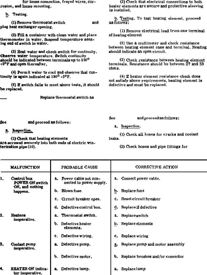
MALFUNCTK)N
1.
2.
3.
4.
control box
POWER ON switch
ON, and nothing
-s.
Heaters
inoperative.
coolant pump
iqoperattve.
HEATER ON indica-
tor inoperative.
T a b l e
4 - 4 .
E l e c t r i c
W i n t e r i z a t i o n
K i t
T r o u b l e s h o o t i n g
PROBABLE CAUSE
a.
b.
c.
d.
a.
b.
c.
a.
b.
a.
Power cable not con-
nected to power supply.
Blown fuse.
Circuit breaker open.
Defective control box.
Thermostat switch.
Defective heater
elements.
Defective wiring.
Defective pump.
Defective motor.
Defective lamp.
CORRECTIVE ACTION
a.
b
-“
c.
d
—“
a.
b
—’
c.
a.
—
b.
a.
Connect power cable.
Replace fuse ( p a r a 4 - 2 8 ) .
Reset circuit breaker ( p a r a 4 - 2 7 ) .
Replace if defective ( p a r a 4 - 2 7 ) .
Replace switch ( p a r a 4 - 2 3 ) .
Replace elements ( p a r a 4 - 2 4 ) .
Replace wiring ( p a r a 4 - 2 6 ) .
Replace pump and motor assembly
( p a r a
4 - 2 2 ) .
Replace brushes and/or connector
( p a r a
4 - 2 2 ) .
Replace lamp ( p a r a 4 - 2 8 ) .
4 - 1 9