Figure 4-8.
noted below when fuel burning winterization kit and
electric winterization kit are used together. (See
sheet 2 of f i g u r e 4 - 7 . )
(1) Disconnect hose (70) from elbow (13) and
elbow (69). Remove nipple (69) from three way valve
( 6 7 ,
f i g .
4 - 1 ) and install plug (64) into three way
valve (67).
(2) Disconnect hose ( 4 2 , f i g . 4 - 7 ) from nipple
(18) and elbow (31). Remove adapter (18) and replace
plug ( 4 9 , f i g . 4 - l ) .
(3) Disconnect hose ( 4 7 , f i g . 4 - 1 ) from elbow
(43) and elbow (50). Remove elbow (43) and replace
plug ( 1 9 , f i g . 4 - 7 ) .
~. Refer to
p a r a g r a p h
4 - 1 8 and replace plugs and
plates removed during installation.
e.
FiLl radiator with proper coolant in accordance
witii t a b l e 2 - 1 and check for leaks.
4 - 2 0 .
P r e v e n t i v e
M a i n t e n a n c e .
To insure that the electric winterization kit is ready
for operation at all times, when installed on the
generator set, ” it must be inspected systematically
so
that defects may be discovered and corrected before
they result in serious damage or failure. Defects
discovered during operation of the kit shall be noted
for future correction, to be made as soon as opera-
tion has ceased. Stop operation immediately
if a
deficiency is noted during operation which would
damage the kit or the end item generator to which it
is attached. All deficiencies and shortcomings
SHALL be recorded together with the corrective
action on the applicable form at the earliest possible
opportunity. Air Force users shall refer to the ap-
plicable inspection manuals and work card sets in
the T . O . 3 5 C 2 - 3 - Series for periodic preventive
maintenance requirements and t a b l e 4 - 3 for detailed
procedure.
4 - 2 1 .
T r o u b l e s h o o t i n g .
T a b l e
4 - 4 provides information useful in diagnosing,
isolating, and correcting unsatisfactory operation or
failure of the electric winterization kit. (See
f i g u r e s
1 - 2 3 ,
1 - 2 6
o r
1 - 2 7 ,
a n d
4 - 6 . )
4 - 2 2 . C o o l a n t P u m p a n d M o t o r A s s e m b l y I n s p e c t i o n ,
T e s t i n g , a n d R e p l a c e m e n t .
a.
Inspection.
Proceed as follows:
(1) See f i g u r e 4 - 7 and inspect motor assembly
for overheating and inspect coolant pump for leaks,
loose connections and loose mounting.
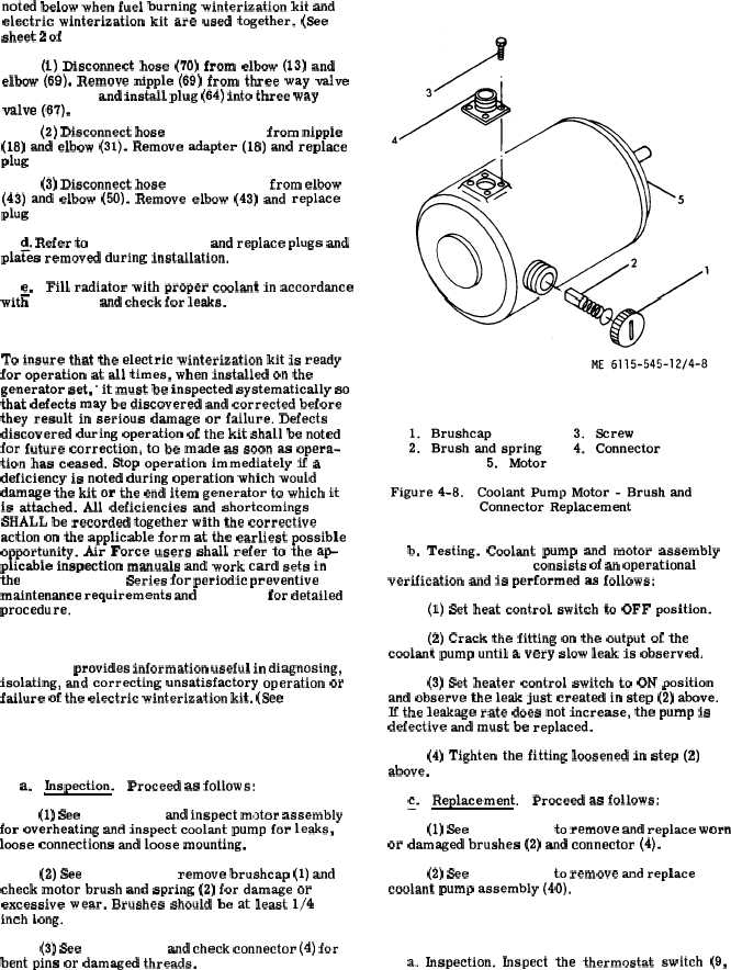
(2) See f i g u r e 4 - 8 , remove brushcap (1) and
check motor brush and spring (2) for damage or
excessive wear. Brushes should be at least 1/4
inch Long.
(3) See f i g u r e 4 - 8 and check connector (4) for
bent pins or damaged threads.
C h a n g e 1
b. Testing. Coolant pump and motor assembly
( 4 0 , f i g . 4 - 7 ) t e s t i n g consists of an operational
verification and is performed as follows:
(1) Set heat control switch to OFF position.
(2) Crack the fitting on the output of the
coolant pump until a very slow leak is observed.
(3) Set heater control switch to ON position
and observe the leak just created in step (2) above.
If the leakage rate does not increase, the pump is
defective and must be replaced.
(4) Tighten the fitting loosened in step (2)
above.
~.
Replacement.
Proceed as follows:
(1) See f i g u r e 4 - 8 to remove and replace worn
or damaged brushes (2) and connector (4).
(2) See f i g u r e 4 - 7 to remove and replace
coolant pump assembly (40).
4 - 2 3 . T h e r m o s t a t S w i t c h I n s p e c t i o n , T e s t i n g a n d
R e p l a c e m e n t .
a. Inspection. fnspect the thermostat switch (9,
4 - 1 8