TM 5-6115-465-34
TO 35C2-3-446-2
NAVFAC P-8-625-34
TM 06858/06859D- 34
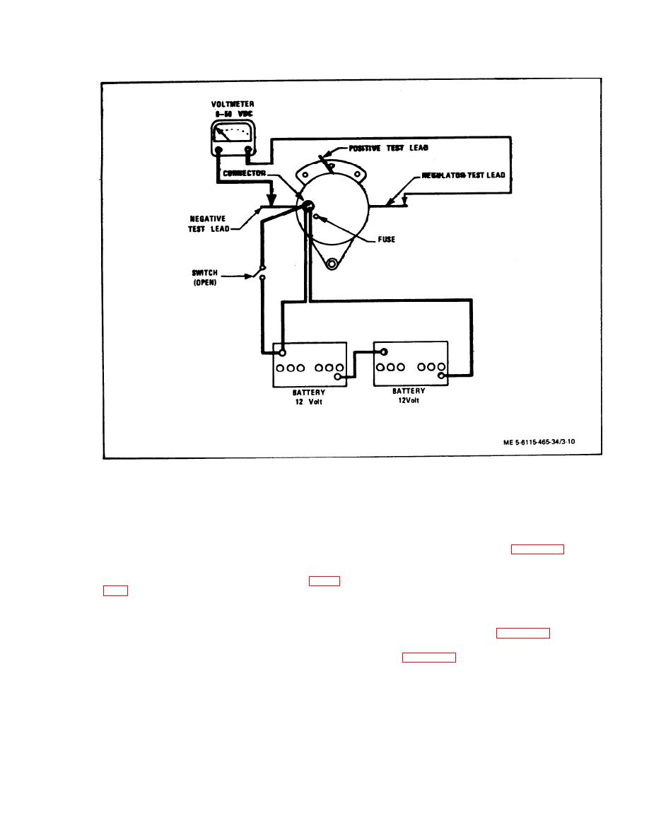
Figure 3-10.
Excitation Voltage Test
and voltage -protector test as outlined in step (10) be-
battery negative terminal and alternator negative
-
low.
output-terminal.
(8) Test for faulty alternator voltage regulator
(c) Correct any discrepancies before
as follows:
comducting operational tests.
(a) Remove screws (1, figure 3-4) and
cover assembly (2).
(6) Coduct excitation voltage test as follows:
(b) Disconnect voltage regulator by discon-
(a) With voltmeter connected as in figure
necting and tagging the red, green and black leads.
(c) Disconnect and tag the blue and yellow
output leads.
(b) Voltmeter should indicate 3.5 0.2
Vdc.
(d) Install a jumper from the GND terminal
to brush terminal as shown in figure 3-11.
(c) If voltmeter indicates zero volts, test
(e) Install alternator in test circuit as
voltage regulator as directed in step (8) below.
shown in figure 3-11.
(d) If voltmeter indication is greater than
NOTE
3.7 Vdc, test for open circuit of alternator field
A means of rotating the alternator at 2000
(rotot) as directed in step (9) below.
to 3000 RPM must be provided. This test
(e) If voltmeter indication is as specified,
can be performed with the alternator in-
proceed with voltage regulator, alternator output,
stalled on an operational generator set,
and operating the set at rated frequency.
3-15


