TM 5-6115-465-34
NAVFAC P-8-625-34
TO 35C2-3-446-2
TM 06858B/06859D-34
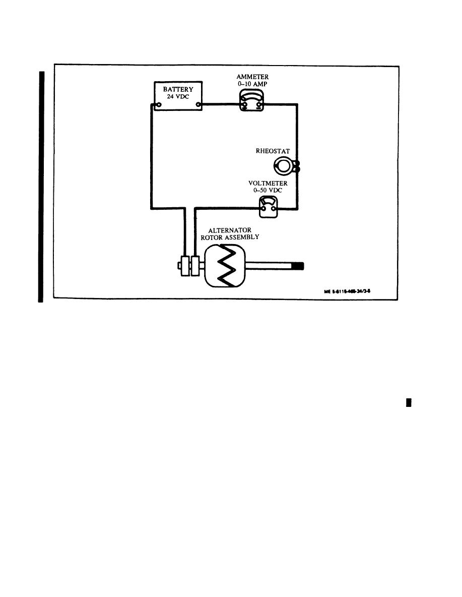
Figure 35. Rotor Assembly Current Draw Test Circuit.
(c) Ammeter should indicate 2.8 to 3.0 amperes at
NOTE
70 to 80F (21 .1 to 26.7C).
The brushes are excessively worn if 3/16 inch or less
(d) High current reading on ammeter indicates low
extends beyond the bottom of the holder.
resistance or a shorted rotor warning.
(14) Check brush spring tension. A force of 4 to 6
ounces should move brush against spring.
rings. Resistance should be 7.5 to 8.0 ohms at an am
(15) Using an ohmmeter, test brushholder assembly
bient temperature of 70 to 80F (21 .1 to 26.7C).
as follows:
(10) Replace rotor assembly if inspection and test
(a) Attach one test lead to brushholder and touch
requirements are not met.
other lead to each terminal and each brush. There should
(11) Inspect voltage regulator connector, cover
be no indication of continuity between brushholder and
assembly, and voltage adjust for cracks, corrosion, and
any terminal or brush.
evidence of shorting or other damage.
(b) Check for continuity between each terminal and
(12) Inspect fuse holder for cracks, corrosion, and
its respective brush.
other damage. Check fuse for burned out condition.
(16) Replace brushholder assembly if inspection and
Check fuse for continuity if in doubt.
test requirements are not met.
(13) Inspect brush assembly for corrosion and ex-
(17) Inspect pulley for excessive wear at pulley
cessive wear.
groove, cracks, corrosion. and other damage.
US. GOVERNMENT PRINTING OFFICE : 1995 0 - 388-421 (02499)
3-10
Change 10
PIN:
013547-010


