TM 5-6115-465-34
TO 35C2-3-446-2
NAVFAC P-8625-34
TM06858B/0685D-34
(e) Close switch (S2) to put carbon pile
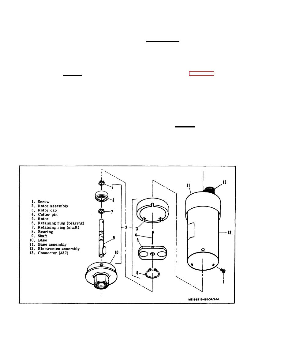
3-6. SPEED SWITCH.
load on the batteries.
a. Removal. Refer to Operator and Organi-
zational Maintenance Manual for speed switch re-
cations. Nominal current output should be 20-25
moval instructions.
amperes with charging voltage exceeding 25.0 Vdc.
b. Disassembly.
(1) Remove screws (1, figure 3-14) to remove
CAUTION
rotor assembly (2) from electronics assembly (12).
Open switch (S2) immediately after
current test to avoid discharging the
(2) Remowe rotor cap (3), cotter pin (4), and
batteries.
rotor (5).
(3) Remove retaining rings (6 and 7), bearing
(8), shaft (9) and base (10).
(g) If nominal voltage cannot be obtained,
disassemble alternator and correct difficulty.
c. Cleaning, Inspection, and Repair.
(h) Remove alternator from test circuit,
remove rear cover assembly and disconnect test
leads.
CAUTION
(i) Reinstall rear cover assembly and
Do not submerge the electronics assembly
fuse.
(12) and base assembly (11) in cleaning
solvent.
f. Installation. Refer to Operator and Organi-
zational Maintenance Manual for battery charging
(1) Wipe the exterior of the electronics as-
alternator installation instructions.
sembly (12) and base assembly (11) with a clean rag,
lightly moistened in cleaning solvent.
Figure 3-14. Speed Switch, Exploded View
3-18


