TM5-6115-465-34
NAVFAC P-8-625-34
T.O.35C2-3-446-2
TM 06858B/06859D-34
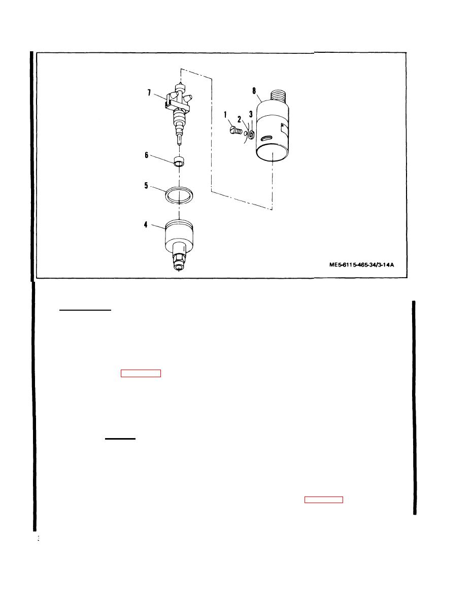
1. Screw
2. LockWire
3. Flat Washer
4. Body Assembly
5. Packing
6 . Spacer
7. Rotor Assembly
8. Cap and Cover Assembly
Figure 3-14.1 Speed Switch. Exploded View Effective with Serial No. RZ70001 and KZ027251 thru KZ027520
assembly for cracks, corrosion, or other damage.
3-6.1. SPEED SWITCH (Effective with serial number
RZ70001 and KZ00001 thru KZ02752).
(4) Replace any worn or defective parts.
Removal. Refer to Operator and Organizational
a.
NOTE
Maintenance Manual for speed switch removal instructions.
There are no repair procedures for the
b.
Disassembly.
cap and cover assembly,
(1) Remove screws (1, figure 3-14.1), lock wire (2)
d.
Test Equipment. The following test equipment
and flat washers (3).
will be required to properly test the speed switch.
(2) Remove body assembly (4), packing (5), spacer
(1) Tachometer test stand or speed switch tester with
(6) and rotor assembly (7) from cap and cover assembly (8),
0.187 tach takeoff fitting, capable of operation up to 1225
RPM.
Cleaning, Inspection, and Repair.
c.
(2) 24 Vdc power supply.
CAUTION
(3) VOM suitable for measuring continuity and 24 volts
Do not submerge the cap and cover
dc.
assembly (8) in cleaning solvent.
(4) Mating connector and cable for MS3102R-18-1P
(1) Wipe the exterior of the cap and cover assembly
connector.
(8) with a clean rag moistened in cleaning solvent.
e.
Testing. Refer to figure 3-15 for schmatic diagram
(2) Clean all other parts with cleaning solvent and dry
of pins to be used during test, and perform the following
thoroughly,
procedures.
(3) Inspect cap and cover, body assembly, and rotor
Change 2
3-18.2


