P-9-TM-457-35
T.O. 35C2-3-442-2
TM-07464A-35
TM 5-6115-457-34
b. If only the accessory drive housing
and drive shaft were removed, proceed as
follow s :
1. Install fuel injection group
2. Install utility governor group
3. Install fuel pump group (para-
graph 8-68).
4. Refer to Operator and Organi-
zational Maintenance Manual and install
secondary fuel filter tank, speed switch,
and hydraulic filter (precise sets only).
c. If drive housing, drive shaft, drive
gear, and idler gear were removed, pro-
ceed as follows:
1. Install fuel injection group
2. Install utility governor group
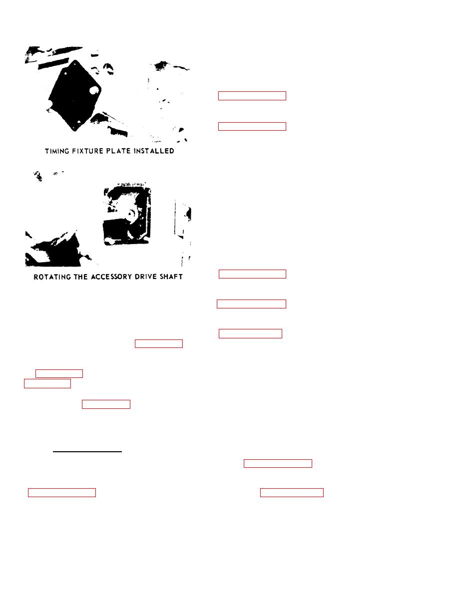
Figure 8-48. Accessory drive shaft timing
3. Install fuel pump group
f. Remove timing plate. Install acces-
sory drive gear as shown in figure 8-30.
4. Refer to Operator and Organi-
Install conical washer with O.D. in contact
with gear, Align timing marks as shown
zational Maintenance Manual and install
in figure 8-30. Tighten retaining nut (1,
secondary fuel filter and relief valve,
speedswitch and hydraulic filter (precise
sets only).
g. Refer to figure 8-29 and install
5. Install crankshaft pulley, damp-
cover (24) and gasket (25) and secure with
er, and timing gear cover group (para-
nuts (22) and lockwashers (23).
graph 8-132).
8-157. INSTALLATION.
6. Install hydraulic pump drive
group (paragraph 8-107).
a. Installation of accessory drive group
is accomplished during reassembly
7. Install hydraulic pump (precise
sets only) (paragraph 8-99).
8-100


