T O 35 C2-3-442-2
P-8-627-34
TM 5-6115-457-34
TM-07464A-35
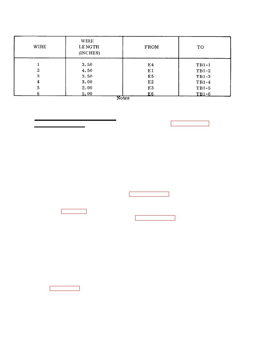
Table 6-12. Electronics Components Assembly (A6) Hook Up Wire Data
1. Solder using Federal Specification Q-Q-S-571, Sn 60
2. Wire is in accordance with MIL-STD-454, requirement 20
6-127. MODE II RELAY BOX ASSEMBLY
1. To isolate a malfunction of the
dc relay, refer to paragraph 6-87.
(A27), 400 HERTZ.
2. To isolate a malfunction of the
6-128. ON EQUIPMENT TEST.
uncle rf requency relay, refer to paragraph
6-107.
a. Symptom and Isolation of Malfunc-
tion. A malfunction of the mode II relay
box assembly is usually indicated by a
3. To isolate a malfunction of the
failure of the dc relay assembly, under-
undervoltage relay, refer to paragraph
frequency relay, undervoltage relay, per-
6-111.
missive paralleling relay, electronic
components assembly, failure of the engine
4. To isolate a malfunction of the
to crank when the start-run-stop switch S2
permissive paralleling relay, refer to
is energized, and unequal reactive and
real load sharing when the generator set
is operated in parallel. To isolate the
5. To isolate a malfunction of the
malfunction, refer to figure 1-16 and pro-
electronic components assembly, refer
ceed as outlined in steps 1. through 8.
WARNING
6. To isolate a malfunction of the
engine crank relay, refer to paragraph
Exercise extreme care not to touch
6-96, step c.
electrical connections when working
on the electrical components with
7. To isolate a malfunction in the
the generator set operating.
reactive droop circuit, refer to paragraph
6-96, step d.
NOTE
8. To isolate a malfunction in the
Remove cover from the mode II
relay box to gain access to the test
real load sharing circuit, measure resis-
points, see figures 6-15 and 6-22.
tance of rheostat R28. Resistance shall
Change 8
6-90


