T O 35C2-3-442-2
P-8-627-34
TM 5-6115-457-34
TM-07464A-35
c. Replace all defective components.
WARNING
Insulating Compound, MIL-I-46058 is
flammable and slightly toxic to eyes,
skin and respiratory tract. Eye and
skin protection required. Good gen-
eral ventilation is normally adequate.
d. After replacement of components,
coat the terminal board with protective
coating, conforming to Military Specifica-
tion MIL-I-46058, grade S, type PUR,
0.005 minimum thickness. Air bubbles
should be prevented during coating, so that
legibility of identification or information
markings are not impaired. The coating
shall be applied so that it anchors the
components to the board. Terminals uti-
lized for connection to external circuits
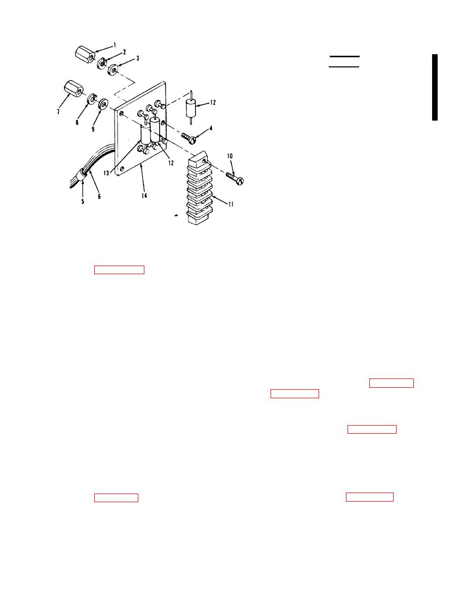
Figure 6-32. Electronic component
shall not be coated.
assembly (A6), exploded view
6-125. REASSEMBLY. Refer to figure
6-32 and reassemble the electronic com-
Legend to figure 6-32:
ponents assembly in reverse order of index
numbers assigned. Pay particular atten-
1.
Standoff
tion to the following.
2.
Lockwasher
3.
Washer
4.
Screw
a. Exercise care not to apply excessive
5.
Cable strap
heat to components when soldering connec-
6.
Wire
tions.
7.
Standoff (2)
8.
Lock washer (2)
b. Connect wires from components to
90
Washer (2)
terminal board according to table 6-12,
10.
Screw (2)
and figure 1-17.
11.
Terminal board
12.
Resistors, R4 and R5
13.
Capacitor, Cl
c. Test electronics components assem-
14.
Terminal board assembly
bly in accordance with figure 6-31.
6-126. INSTALLATION. Refer to figure
6-124. REPAIR.
6-22 and install the electronic components
assembly in the mode II relay box. Secure
a. Repair or fabricate electronics com-
the relay in position with three screw as-
ponents assembly hookup wire in accord-
semblies, then refer to figure 1-17 and re-
ante with table 6-12.
connect wiring. Replace mode H relay
b. Restencil all illegible reference
box cover.
designations.
6-89
Change 8


