T.O. 35C2-3-442-2
P-9-TM-457-35
TM 5-6115-457-34
TM-07464A-35
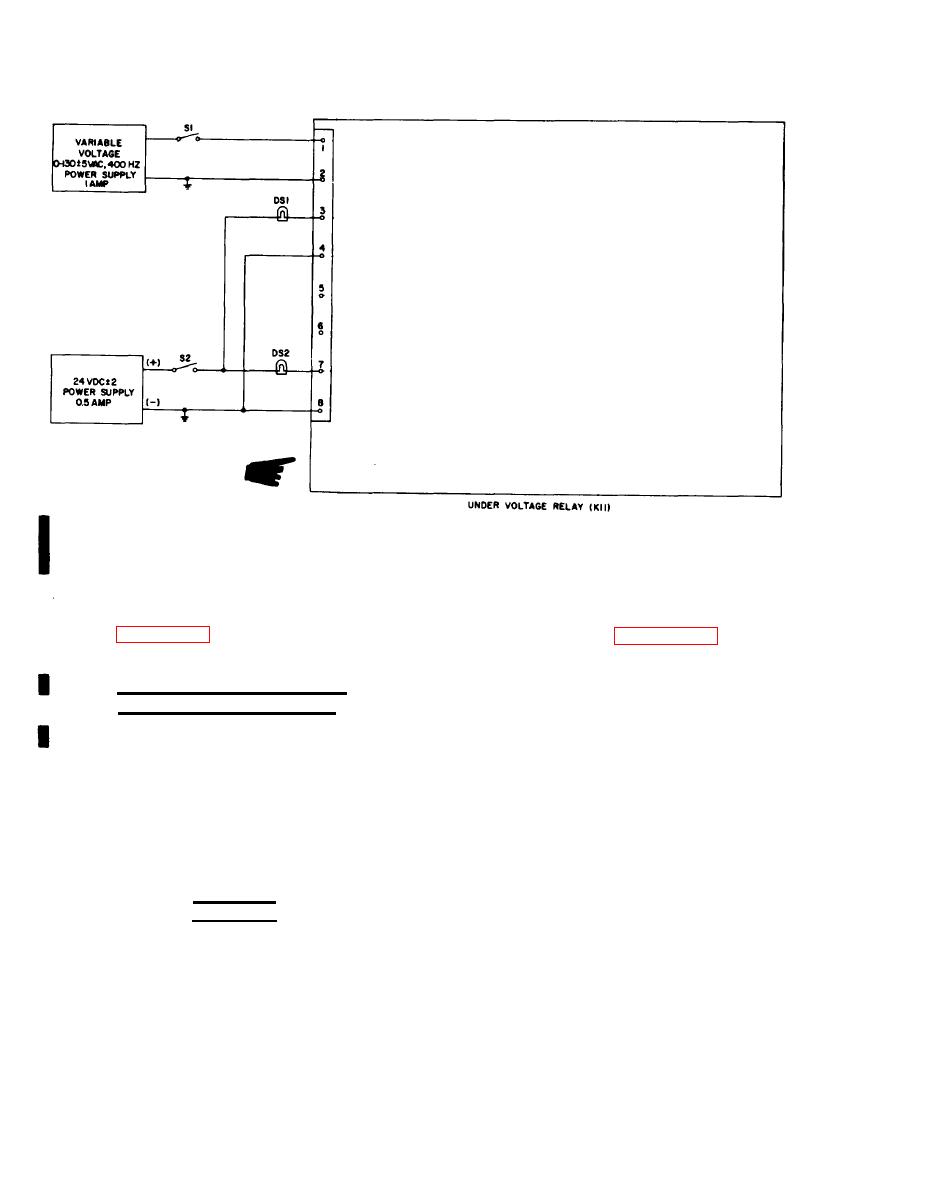
Figure 6-29. Undervoltage relay (K11), test setup
6-113. INSTALLATION. Refer to figure
NOTE
6-22 and install the undervoltage relay in
the mode II relay box. Secure the relay in
Remove cover from mode II
position with four screw assemblies, then
relay box to gain access to the
refer to figure 1-17 and reconnect wiring.
test points, see figures 6-15
and 6-22.
Replace mode II relay box cover.
6-114. PE RMISSIVE PARALLELING
1. Remove wire from terminal 7 of
RELAY (K16), 400 HERTZ.
the K16 relay to prevent the contacts from
closing. With the generator set operating
6-115. ON EQUIPMENT TEST.
at rated speed and voltage and the-load buss
energized by a second set, measure the
a. Symptom and Isolation of Malfunc-
voltage from terminal 3 to terminal 4 of
tion. A malfunction of the permissive
the K16 relay. The voltage should read
paralleling relay K16 is usually indicated
20-32 VDC.
by the load contactor CB2 closing when the
set voltage is out of phase with the buss
voltage. To isolate the malfunction, pro-
2. Measure the voltage from terminal
ceed as follows:
1 to terminal 2 of K16 with the contactor
switch (S3) in the close position. Connect
WARNING
an ohmmeter across terminal 7 and 8 of
Exercise extreme care not
K12. Observe that the ohmmeter does not
to touch exposed electrical
read continuity when the voltage across
terminals 1 and 2 is above 10 VAC; if the
connections when working
contacts close with a higher voltage the K16
inside mode II relay box with
relay is defective.
generating set operating.
Change 3
6-86


