T.O. 35C2-3-442-2
P-9-TM-457-35
TM-07464A-35 TM 5-6115-457-34
applied. To isolate the malfunction proceed
as follows:
Exercise extreme care not to touch
electrical connections when work-
ing on the exciter-regulator assem-
bly with the generator set operating.
NOTE
Remove cover from exciter regu-
lator to gain access to test points,
see figure 6-15.
1. With the generator set operating
at rated speed, measure the voltage across
(A10)TB1-7 and (A10)TB1-8 (nominal volt-
age is 105 VAC). Refer to figures 1-10 and
1-12. If sensing voltage at TB1-7 and
TB1-8 is normal measure voltage across
(A10)TB2-6 and (A10)TB2-7, minimum volt-
age should be 50 VAC.
(a) If there is no voltage at
TB2-6 and TB2-7 measure voltage across
(A11)TB2-2 and (A11)TB2-3 which is the
generator coil voltage (T9-T12). Shut down
generator set if voltages are normal.
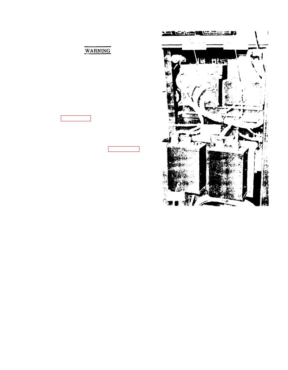
Figure 6-15. Location of exciter
regulator and mode I, mode II,
(b) Measure for continuity from
precise and tactical relay
plug P11 pin H to plug P11 pin G, the read-
assemblies
ing should be 21 ohms. Pins G, and H of
J11 should read 13 ohms, observe polarity.
(a) If flashing voltage is ob-
(c) If circuit is open replace ex-
served connect an ac voltmeter (0-150 volt
citer (A11). If all readings are normal,
scale) across choke (A11)L1 and observe
replace regulator (A10).
for ac voltage when the field is flashed.
(b) If voltage is observed across
2. To check exciter regulator per-
choke but the generator output voltage does
formance when there is no generator output
not build up, shut down generator set and
voltage, connect a dc voltmeter (0-50 volt
check for shorted diode CR1, CR2, CR3, or
scale) across resistor (A11)R17 and observe
CR4. If diodes are shorted, replace the
for field flashing voltage when generator
exciter.
set is started.
6-41


