TM 5-6115-400-35
The usual equipment used with the valve seat grinder
set includes the following items:
(a) Valve seat grinder.
(b) Dial gauge.
(c) Tool pilot.
(d) Four grinding wheels: 150, 300, 450,
and 600.
(3) The cutting face of the stone must be
maintained at the correct angle and in
proper condition by frequent dressing with
a diamond wheel dresser. The frequency
of dressing will be determined by
condition of the seats and amount of
metal required to be removed during the
grinding operation.
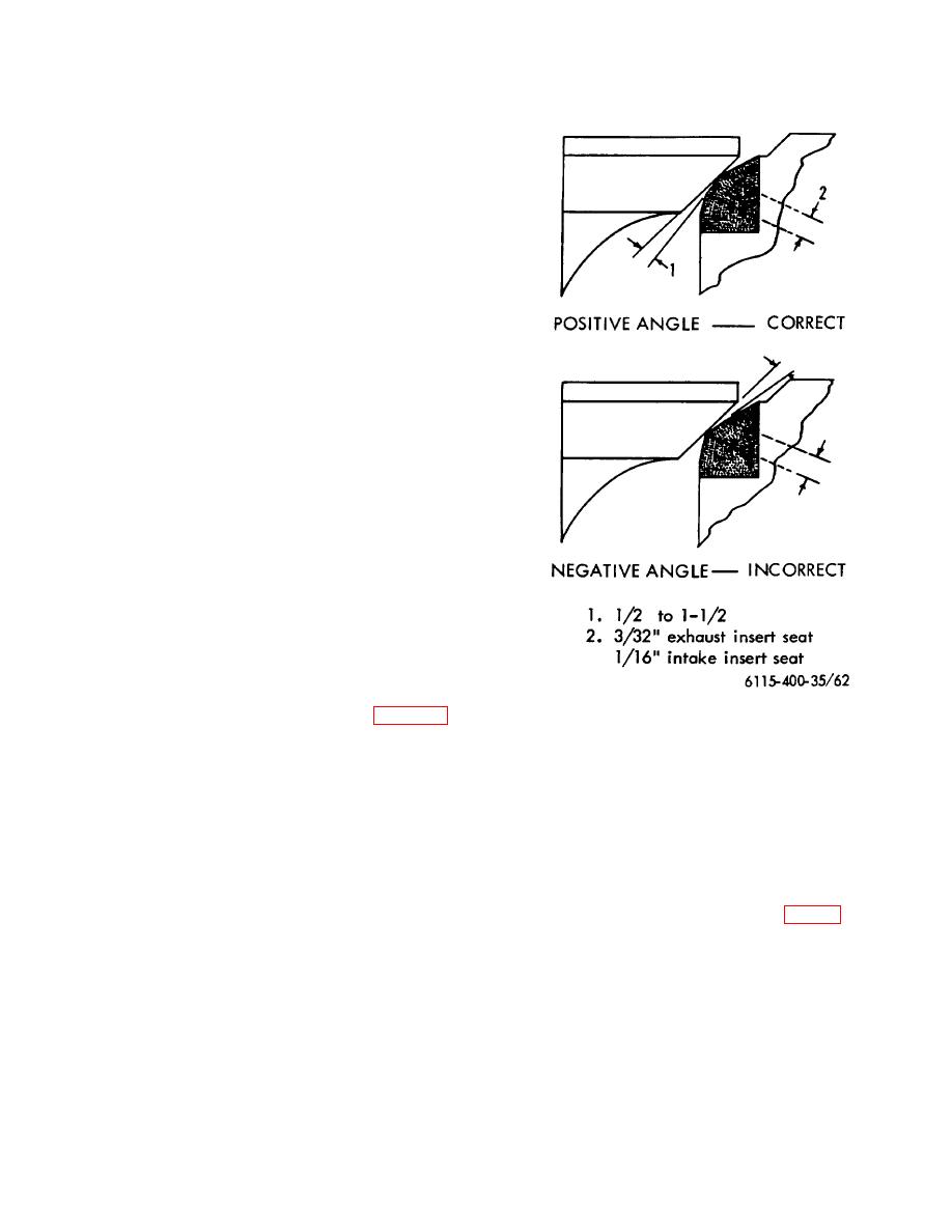
(4) By grinding valve face and insert seat at
slightly different angles, a fine line contact
of the face and seat is obtained, thus
eliminating the need to lap the seating
surfaces with grinding compound.
(5) The difference of angles is termed
0
"interference angle" and is usually 1/2 to
0
1 1/2 . The angle of the insert seat is
made greater than that of the valve face,
so as to assure contact at the top of insert
seat. Thus, for the 450 exhaust valve
0
face angle and a 1 interference angle,
the insert seat grinder wheel must be
dressed to grind the insert seat at an
angle of 460. Likewise, the insert seat for
0
the intake valve must be ground at 31 .
This is a positive interference angle. A
Figure 62. Interference angle.
negative angle, as illustrated in figure 62,
film of Prussian Blue on the valve face
must be avoided.
The first step in
and bounce the valve once on the valve
reconditioning the insert is to grind the
seat. A thin, continuous line must be
seat, removing only enough metal to
evident on the valve face, otherwise
produce a pit-free continuous seat. After
further grinding is required.
seat has been ground, use a dial gauge to
Note
check concentricity of the seat relative to
Do not revolve valve while checking
the valve guide. The total run-out of a
good seat should not exceed .002 inch
seat.
total indicator reading.
The specified width of the valve seat on
the insert is 3/32 inch for the exhaust and
(6) To determine seat contact in relation to
1/16 inch for the intake (fig. 62). If the
insert and valve face, wipe a thin
seats are too wide or too narrow they
must be ground to the specified width
using the appropriate angle grinding
wheels.
95


