TM 9-6115-660-13&P
3. Remove insulation from W9-20 and W9-49 connections to resistor R3 and unsolder harness leads.
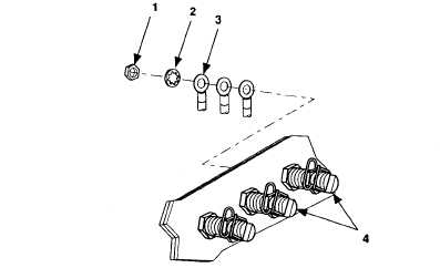
4. Remove nut (1, figure 5-11), internal tooth washer (2), and W9 harness lead (3) from load terminals
L0 and L3 (4).
Figure 5-11. Switch Box Load Terminals.
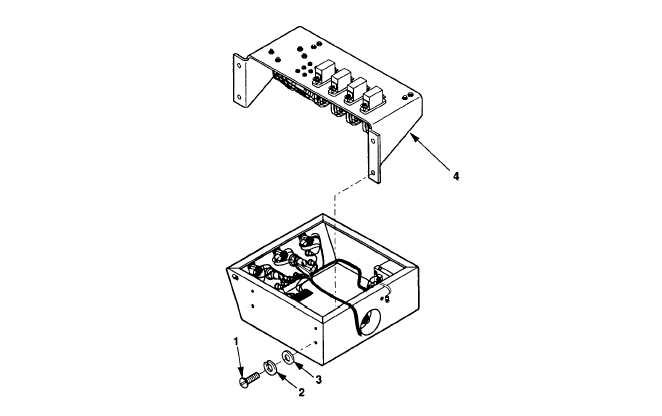
5. Remove four screws (1, figure 5-12), internal tooth washers (2), and flat washers (3), and invert relay
board assembly (4).
Figure 5-12. Relay Board Assembly Removal.
5-19


