TM 9-6115-658-13&P
2-26
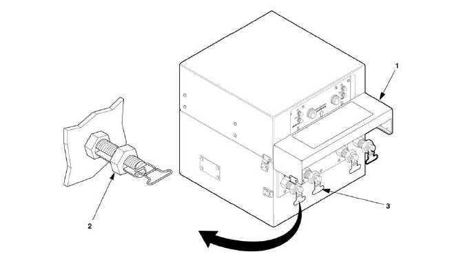
Figure 2-7. Switch Box Load Cable Connections.
b. Select required output terminals from Table 2-3.
Table 2-3. Load Terminal Voltage
GENERATOR
OUTPUT
TERMINALS
VOLTAGE
READING
120V 1PH
L1 - N
120 VOLTS
120/240V 1PH
L1 - L2
L1 - N
L2 - N
240 VOLTS
120 VOLTS
120 VOLTS
c. Using load terminal box wrench located in accessory box, loosen terminal nuts (2) on
terminals (3) selected from table in step b.
d. Insert ends of cables into slots of load terminal studs (3).
e. Tighten load terminal nuts (2) and close clip and load terminal cover (1).
2-3.5 Positioning of Fire Extinguishers. Remove fire extinguisher(s) (Figure 1-2) from bracket(s) on trailer.
Locate fire extinguisher(s) on ground away from power plant.
2-4 INITIAL ADJUSTMENTS, CHECKS, AND SELF TEST.
Refer to Table 2-2 and perform all "Before" PMCS. Refer to TM 9-6115-639-13 and perform generator set initial
adjustments, checks, and self-tests.