TM5-6115-593-34
NAVFAC P-8-631-34
TO-35C2-3-463-2
(c)
Assembly spring (102), buffer
piston (103), spring (102, packing (101),
buffer plug (100), and retaining ring (99) in
case.
NOTE
Insert buffer piston (103) into case correctly
with cup ent out.
(8)
Assembly needle valve (92) in case (figure 12-
13).
(9)
See figure 12-14.
(a)
Assembly power piston (152) and
floating lever (142) with pin (138) and ring
(149).
(b)
Assemble pivot link (148) and
terminal lever link (147) with pin (140), and
fasten together with roll pin (139).
(c)
Assembly terminal lever (146) to
terminal lever link (147) with pin (143).
(d)
Assembly pivot pin (81) to piston link
(83)with straight pin (80).
(10)
Insert power piston (152) and floating lever (142)
assembly into case per figure 12-15.
(11)
Insert terminal lever (146), terminal lever link
(147) and pivot link (148) into the case (figure 12-
16). Insert floating lever (142) through the slot in
pivot link (148). Fasten together with pin (141)
and secure with a cotter pin.
(12)
Insert piston link (83) and pivot pin (81) into top
hole in power piston. Secure with washer (82)
and cotter pin.
See figure 12-3.
(13)
Refer to figure 12-17 and 12-18.
(a)
Insert pin (134) into power piston
(133). Place this assembly in case.
(b)
Attach solid end of piston link
(34) to power piston (133) with headed pin
(131), washer (32) and secure with a cotter
pin.
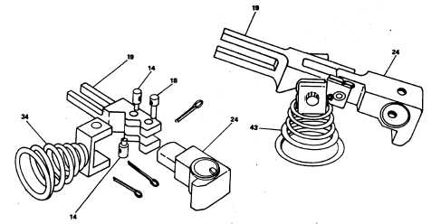
Figure 12-8. Speeder Spring Subassembly
12-11