TM 5-6115-593-34
NAVFAC P-8-631-34
TO-35C2-3-463-2
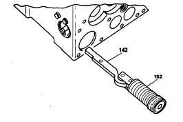
Figure 12-15. Power Piston Assembly
valve plunger is centered, tighten nut (84),
figure 12-22, to 70 inch-pounds (8 joules).
(20)
Lubricate base oil seal (118, figure 12-24) and
place it in groove on base. Line up pins (107).
Assembly base to case and secure it with
lockwashers (106) and screws (105). Check
bushing rotation for freeness before tightening
screws.
(21)
Assembly transducer cup (75), transducer
solenoid (76), washer (77), magnet (78), and
coil cover (79). See figure 12-25. Plug (51) is
attached to the transducer.
(22)
Install transducer assembly on pilot valve
plunger and attaching plug (51) to case with
screws (50). Be sure connections of plug (51)
match the connections in cover.
(23)
Install clamp bracket assembly (74, figure 12-3)
with screws (65) and lockwasher (66). Line up
guide pin on bracket (74) with slot in link (83).
Insert centering screw (63) through hollow
center of adjustable spring seat (64). Bottom
centering screw to prevent binding when plate
(70) is installed. Final adjustment is made later.
(24)
Insert transducer compression spring (57) in
position and pivot the transducer lever over to
lie on top of the spring. Attach plate (70) to
restoring lever with
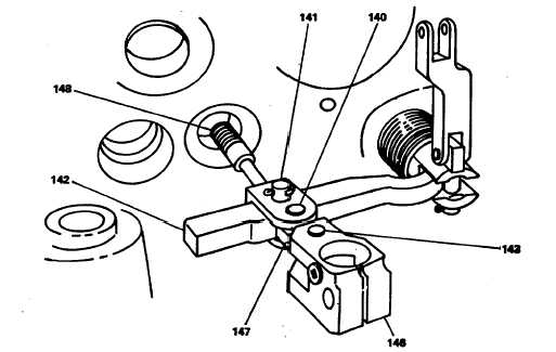
Figure 12-16. Power Piston and Linkage Installation
12-15