TM5-6115-593-34
NAVFAC P-8-631-34
TO-35C2-3-463-2
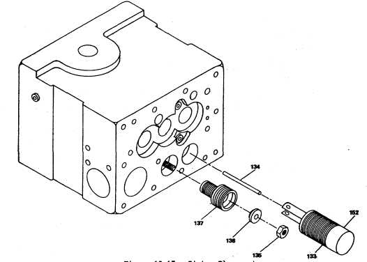
Figure 12-17. Piston Placement
screws (67) and washers (68 and 69).
(25)
Insert terminal shaft (46, figure 12-26) through
side of case (figure 12-26) and through terminal
lever (146). Insert tapered pin (33) into hole tight
enough for alignment and thread screw (144) with
washer (145) into terminal lever (146). Insert
tapered pin (44) into hole tight enough for
alignment and thread screw (144) with washer
(145) into terminal lever and tighten. Tap taper
pin until it is tight.
(26)
Assembly speed droop adjustment bracket (32,
figure 12-27) on speed droop lever (33) with
screw and washers (29, 30, and 31).
(27)
Lubricate packings (42, figure 12-28 and place on
speed pivot pins (41). Place speed droop-lever
assembly in the case in line with hole above
terminal shaft (46). Insert pivot pins (41) on both
sides of case through holes into speed droop
lever. Secure pivot pins with retaining rings (40).
(28)
Attach dial plates (38 and 39) with screws (37,
figure 12-29). Place oil seal (48, cup towards
case) and washer (49) on terminal shaft. Turn
terminal shaft to maximum position. Place
pointers (36) on terminal shaft with pointer
pointing at MAX., and secure them in place with
retaining ring (35). Adjust dial plate (38) until
MAX, line and
12-16