TM5-6115-593-34
NAVFAC P-8-631-34
TO-35C2-3-463-2
(c)
Place piston (137), pivot washer (136),
and elastic stop nut (135) into the case as
shown. Threat nut (135) onto pivot link (148)
nine to nine and a half turns.
(d)
Tighten and loosen nut (135) until no
pivot motion exists between power pistons (152
and 133). Optimum adjustment is when the
pistons have no play and are not tight.
(14)
Refer to figure 12-19 and place packing (l119) in
base. Lubricate and put packing (112) on plug
(111) and push into base. Put spring washer
(150) (concave side up) in place on top of plug
(111) in base.
(15)
Refer to figure 12-20.
(a)
If idler gear stud (125) has been
removed (although this should not be
necessary), press it into case until its end
is just below face surface.
(b)
Insert pilot valve bushing
assemblies (120 and 126) and idler gear
(124) into case as shown. Gears should
all mesh.
(16)
Refer to figure 12-21.
(a)
Lubricate packing (151) and place it on
load sensing sleeve (153) and insert sleeve into
case.
(b)
Insert sleeve (116), plunger (115),
spring (112), and spacer (114) into case.
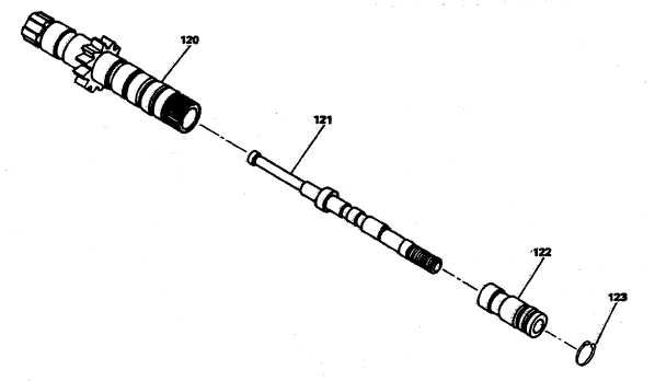
(17)
Place ballhead assembly (91) in case on pilot
valve plunger (121). Secure with retaining ring
(87). (See figure 12-22.) :
(18)
Install thrust bearing (86), speeder spring seat
(85) on pilot valve plunger (121) and secure with
nut (84). Do not tighten nut (84).
Figure 12-9. Governor Pilot Valve Assembly
12-12