TM5-6115-593-34
NAVFAC P-8-631-34
TO-35C2-3-463-2
of case to knock out the oil seal (22).
(5)
Remove speed adjusting shaft (23), speed
adjusting lever (24), bushings (25) and spacer
(26). Do not remove bushings (25) unless they
need replacement.
(6)
Remove speed droop lever pin (28) connecting
speed droop lever (33) and piston link (34).
(7)
Remove two rings (35) and both dial plates (38
and 39) from the case (157).
(8)
Remove retaining ring (40), pull out pivot pin (41)
and take out speed droop lever (33).
NOTE
If the speed droop bracket is removed,
mark its position on the speed droop
lever for ease in reassembly.
(9)
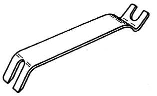
Use pilot valve wrench, figure 12-5, and place it
between speeder spring (43) coils on spring seat
(85). Disengage spring from its seat. Hold seat
with wrench and bend spring towards open end of
bottom coil. At the same time turn spring to
disengage coil from seat lip.
(10)
Remove taper pin (44) from terminal lever (146)
using
Figure 12-5. Pilot Valve Wrench P/N 370109
a 10-32 nut and two washers from the cover as a puller.
(11)
Remove retaining ring (45) from terminal shaft
(46) and pull shaft from case. Remove bushings
(47) only if replacement is necessary, oil seal (48)
and washer (49) from both sides of the case.
(12)
Remove screws (50) that attach plug (51) to case.
Do not disconnect plug from solenoid leads.
(13)
Remove pin (53) and disconnect restoring lever
(72) from piston link (83).
(14)
Remove pin (54) from transducer bracket (74).
Lift out transducer lever (58), spring seat (56) and
spring (57).
NOTE
If spring seat is to be removed from transducer
lever, measure and record projection of seat
above top of transducer lever for ease in
reassembly.
(15)
Remove screw (63) and restoring spring
assembly (64) including attached parts (59)
through (62).
(16)
Remove screws and lockwashers (65 and 66) and
lift out transducer bracket assembly (74, 72, 71,
and 67 through 70).
NOTE
If ratio adjustment plate (70) is
removed, mark its position on
restoring lever (72) so it can be
replaced in the same position.
(17)
Lift out temperature compensation cup (75),
solenoid (76), washer (77), magnet (78), and
cover (79) as a unit. Do not remove spring (129)
from pilot valve plunger.
(18)
Remove pivot pin (81) and piston link (83).
12-8


