TM5-6115-593-34
NAVFAC P-8-631-34
TO-35C2-3-463-2
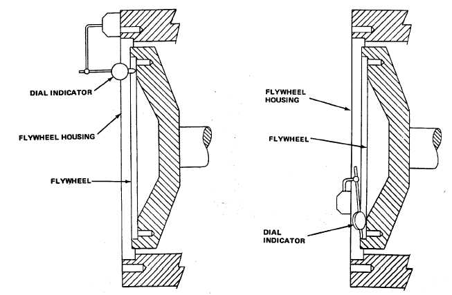
Figure 11-6. Checking Flywheel Face Runout
Figure 11-7. Checking Flywheel Pilot Bore Eccentricity
(e)
Measure the distance from the surface on the
generator adapter that bolts to the engine flywheel
housing to the outside surface on the drive discs
(Dimension "Y", figure 11-9). Then measure the
distance from the machined surface on the engine
flywheel (Dimension "C", figure 11-10). If the
distance from the bellhousing to drive disc recess
"C" is more than the distance from the generator
adapter to the drive discs "Y", install additional
spacers between the drive discs and the generator
drive hubs. If "Y" is more than "C", remove spacers
located between the drive discs and generator hub.
(f)
Make certain drive discs "seat" in the drive disc
recess.
WARNING
NEVER GRIND OD OF DRIVE DISCS
AND NEVER ATTEMPT TO "DRILL
OUT" HOLES IN DRIVE DISCS. IF
DRIVE DISCS DO NOT FIT PROPERLY,
REPLACE DRIVE DISCS.
(3)
Locating Generator. Lift the generator by attaching
an overhead hoist and slings to the eyebolts on the
generator frame.
11-16