TM5-6115-593-34
NAVFAC P-8-631-34
TO-35C2-3-463-2
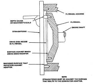
Figure 11-8. Checking Flywheel Housing Runout
CAUTION
Determine that the hoist is of sufficient
strength to adequately support the
weight of the generator. Hoist and
Hoist cables should have a rating of
not less than 6,000 pounds (2,727 kg).
Always make certain extreme care is
taken when moving the generator to
prevent its striking other objects or
personnel. Never apply a lifting force
to structural points other than those
provided for that purpose.
(a)
Install sixteen screws and washers securing
generator assembly (figure 11-5) and six
bolts and locking plate to engine flywheel
housing. Tighten screws.
(b)
Move generator to location on skid base,
line up mounting holes
and install four generator mounting bolts
(figure 11-5) securing generator frame to
the skid base assembly. Do not tighten
bolts at this time.
(c)
Install Control Box Assembly per
paragraph 2-14b.
CAUTION
If fan is moved, make certain that
before generator set is placed in
operation, fan is positioned with
about 1/2 inch (13 mm) clearance
between fan and baffle and all fan
bolts are installed and tightened .
(d)
Tighten mounting bolts to torque shown in
figure 11-5. Make certain generator
mounting pads contact the base evenly and
with equal pressure. Use of shims may be
required.
(e)
After generator is assembled to the engine,
check runout by placing the base of a dial
indicator on a generator frame rib and
positioning the indicator finger on the
generator shaft. Set dial indicator to zero.
Turn generator through at least one
revolution. Total indicator reading should
not exceed 0.005 inch (0.13 mm).
NOTE
Use inspection mirror to read indicator. It
may be necessary to move fan out of the
way. See CAUTION following step (c).
(4)
Installing PMG.
(a)
Install the exciter rotor assembly and the
pilot exciter rotor. Make certain the key is
in place in the shaft before installing exiter
rotor assembly.
CAUTION
Do not apply force to rotating rectifier
or to the armature windings.
11-17