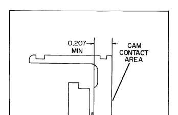
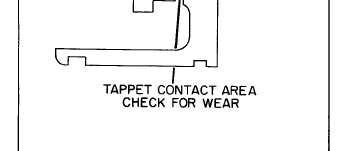
Figure 7-37. Inspecting Tappet
(5) Inspect the tappet (20) for possible wear at
the contact areas. The primary contact areas are the
tappet contact area and the cam contact area (figure
7-37). Replace the tappet if wear indentations exceed
0.002’. The tappet thickness measured between the
plunger button contact surface and the cam contact
area must be 0.207” or larger.
(6) The pump housing (6, figure 7-34) should be
washed in a cleaning solvent. Check all the screw
threads in the housing, damaged threads can be re-
paired using thread inserts.
(7) Examine the pump housing for cracks or
other damage which will cause oil leakage. Replace
cracked housings.
NOTE
The control unit assembly is serviceable as a
unit only. Each control unit assembly is fur-
nished with a factory fitted plunger sleeve pin.
(8) Holding sleeve of control unit assembly (4),
rotate lever; shaft must turn freely. If a binding
condition exists, wash assembly in a cleaning agent,
and repeat procedure. If binding condition is still
present, control unit assembly must be replaced. Also
check to make certain that weld holding lever to shaft
is intact.
(9) The flat end of plunger sleeve pin (5) must be
checked for clearance in the mating slot of the
plunger sleeve. If the clearance is greater than 0.0015”,
the entire control unit must be replaced.
TM5-6115-585-34
NAVFAC P-8-262-12
TO-35C2-3-455-2
TM-05684C-34
(10) Plunger sleeve pin (5) must fit snug but must
be free to rotate in control unit assembly.
NOTE
New part clearance is 0.0002-0.00081". If
clearance exceeds 0.0015”, replace control
unit assembly.
d. Reassembly (see figure 7-34).
NOTE
Replace all copper and “O" ring gaskets.
(1) After all parts have been thoroughly cleaned
and inspected and after all worn units have been re-
placed, dip the individual parts in clean fuel oil.
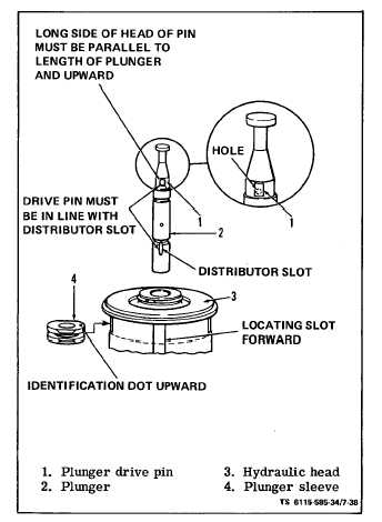
(2) Invert the hydraulic head (17) and place it on
a clean bench so that the head locating slot is forward.
(3) Refer to figure 7-38 and align the plunger
drive pin (1) into the plunger (2) so that the head of
the plunger drive pin is in the line with the distribu-
tor slot. Turn the plunger drive pin until its long side
is parallel to the length of the plunger with long end
up.
Figure 7-38. Assembling Hydraulic Head
7-35