TM5-6115-585-34
NAVFAC P-8-262-12
TO-35C2-3-455-2
TM-05684C-34
1. Retaining plate screw (2)
14. Copper gasket
27. Spring ring
2. Tab washer (2)
15. Head retaining screws (4)
28. Face gear
3. Control unit retaining plate
16. Head retaining clamps (4)
29. Thrust washer
and stop assembly
17. Head assembly
30. Plunger drive pin
4. Control unit assembly
18. Head"O" ring
31. Timing screw
5. Plunger sleeve pin
19. Head “O” ring
32. Gasket
6. Pump housing
20. Tappet
7. Cap nut
33. “O” ring
21. “O” ring
34. Plunger sleeve
8. Gasket
22. Button spring ring
35. Plunger
9. Delivery valve holder
23. Plunger button
36. Control unit bore
10. Valve spring
24. Lower spring seat washer
37. Pin
11. Delivery valve assembly
25. Seat
38. Flatwasher
12. Valve spacer
26. Plunger spring
39. Lockwasher
13. Locating screw
40. Nut
TS 6115-585-34/7-34(2)
Figure 7-34. Disassembly of Fuel Injection Pump (Sheet 2 of 2)
(7) Remove the hydraulic head locating screw (13)
and copper gasket (14).
(8) Remove the four head retaining screws (15)
and the four head retaining clamps (16). Carefully
rest tappet on clean surface and using shaft head,
hammer pump body assembly until hydraulic head
assembly separates from body assembly.
(9) Remove the “O” rings (18 and 19) from the
hydraulic head and the pump housing.
(10) Remove the tappet (20) and related “O” ring
(21) from the face gear bore.
(11) Remove the spring ring (22) and the plunger
button (23) from the end of the plunger (the plunger is
part of hydraulic head assembly).
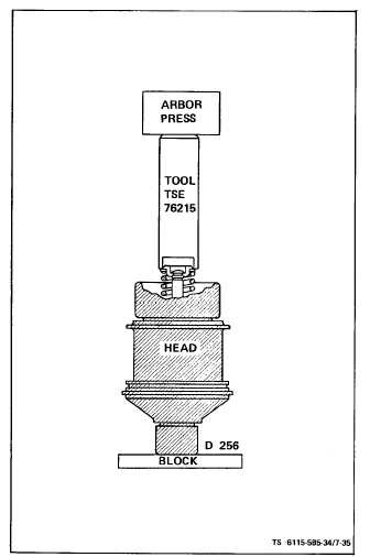
(12) Invert the hydraulic head assembly and place
it in a suitable arbor press (see figure 7-35).
(13) Position tool TSE 76215 over the lower spring
seat washer (24, figure 7-34) and depress the plunger
spring, then remove the lower seat (25).
(14) Remove lower spring seat washer (24, figure
7-34) and plunger spring (26).
(15) Place the hydraulic head assembly on a
bench. Using two screwdrivers to carefully pry off
the face gear (28), then remove the thrust washer (29).
(16) Do not remove the plunger (35) out of the
hydraulic head.
NOTE
The Plunger, Plunger Sleeve and Hydraulic
Head are mated Parts and must ALWAYS be
kept together.
c. Inspect (see figure 7-34).
(1) Place the delivery valve assembly in test
fixture TSE 76226 and secure in a suitable vise (see
figure 7-36).
Figure 7-35. Removing Lower Spring Seat
7-33