TM5-6115-585-34
NAVFAC P-8-623-34
TO-35C2-3-455-2
TM-05684C/05685B-34
(14) Refer to paragraph 7-8 and install alternator
stator.
(15) Refer to paragraph 7-7 and install blower
wheel.
(16) Refer to paragraph 7-9 and install cylinder
heads.
(17) Refer to Operator and Organizational
Maintenance Manual and install blower housing.
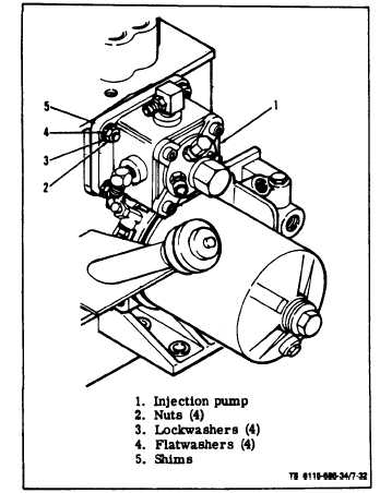
7-18. FUEL INJECTION PUMP.
a. Removal (see figure 7-32). On ASK equipped generators,
refer to Operator and Organizational Maintenance Manual and
remove top panel end right panel assemblies.
(1) Snap off governor linkage from injection pump (l), and
governor control arm and remove linkage.
Figure 7-32. Injection Pump
(2) Refer to paragraph 7-2 and disconnect inlet
and fuel return lines from pump. Tag and disconnect
high pressure lines at injector nozzle end at injector
pump. .
NOTE
All fuel connections must be plugged or capped
to prevent contamination.
7-30
Change 6
(3) Remove four hexagon nuts (2, figure 7-32),
lockwashers (3), and flatwashers (4) holding pump (1)
to crankcase and lift pump off crankcase. Be careful
to retain the shims (5) between the crankcase and
pump. The correct thickness of shims as stamped on
the crankcase is important to proper pump operation;
it provides the proper gear lash. This thickness does
not change when a new pump is installed. It changes only when
a new cylinder block is installed. To calculate new shim thickness
measure between camshaft and engine block pump mounting sur-
face. Substract that measurement from 1.171 inches. This will be
the shim thickness. Refer to figure 7-33A. Use Gage, Depth,
Micrometer NSN 5210-00-542-4602 for this measurement.
(4) When removing a pump for replacement, re-
cord the button thickness and port closing dimensions
as stamped on the side of the pump mounting flange
(figure 7-33). These values are important in timing a
new pump to the engine.
b. Disassembly (see figure 7-34). All work on in-
jection equipment MUST be performed in the cleanest
location possible. No filing, scraping or sawing should
be done on the bench where repairs are made.
(1) Clean all external dirt and grease from the
pump.
The Pump Housing Must NEVER Be Clamped
in a Vise.
NOTE
A special mounting fixture
must be made to adequately
housing.
(see table 2-2)
secure the pump
(2) Clamp the mounting fixture in a suitable vise.
(3) Install the pump into the mounting fixture,
with two 0.3125’’ -18 UNC-HEX head screws.
(4) Release lock tabs (2) and remove the two con-
trol unit retaining plate screws (1) and tab washers
(2, figure 7-34) and the control unit retaining plate
and stop assembly (3). Care fully pull the control unit
assembly (4) with plunger sleeve pin (5) out of the
pump housing (6). Plunger sleeve pin occasionally may
have to be removed separately. Use needle nose pliers
or magnetic pencil.
(5) Remove the delivery valve cap nut (7) and
gasket (8).
(6) Remove the delivery valve holder (9) then
lift out the delivery valve spring (10), delivery valve
assembly (11) and delivery valve spacer (12).