TM5-6115-585-34
NAVFAC P-8-262-12
TO-35C2-3-455-2
TM-05684C-34
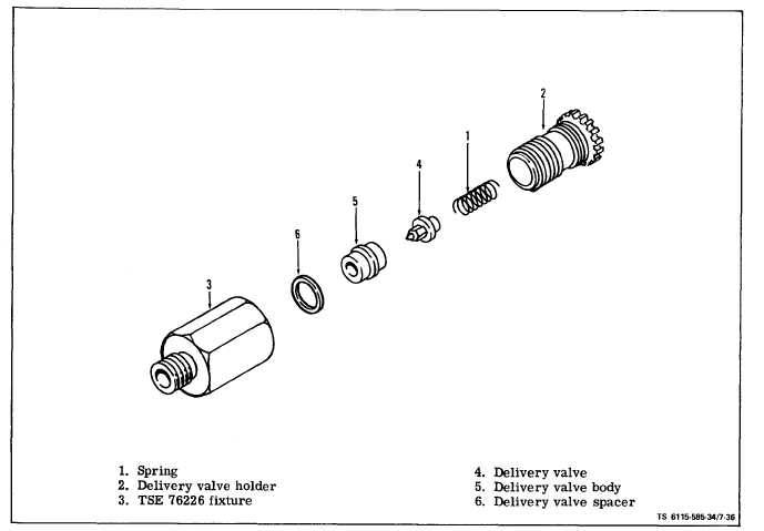
Figure 7-36. Delivery Valve Test Assembly
(a) Insert the delivery valve spring (1) and the
delivery valve holder (2). Tighten the delivery valve
holder to a torque of 70-75 ft-lbs. Figure 7-36 illus-
trates the components that are to be assembled to
test fixture TSE 76226 (3).
(b) Attach test fixture TSE 76226 (3) to a manual-
ly operated Nozzle Test Stand.
NOTE
Always check to make certain that all external
connections are tight and that the Nozzle Test
Stand is in good order.
(c) Delivery valve opening pressure is 300-600
psi. Delivery valve must hold 275 psi for 30 seconds.
Remove delivery valve assembly from test fixture.
The delivery valve spring (1) must be free of nicks or
wear (flat spots). Always replace nicked or worn
springs.
7-34
LAPPING COMPOUND MUST NOT COME IN
CONTACT WITH THE RELIEF PISTON DUR-
ING THE LAPPING OPERATION, AND ALL
LAPPING COMPOUND MUST BE REMOVED
BEFORE
INSTALLING THE DELIVERY
VALVE ASSEMBLY INTO THE HYDRAULIC
HEAD.
(d) If the delivery valve assembly is leaky,
the delivery valve seat may be lapped to its corres-
ponding seat in the delivery valve body with a small
quantity of suitable Lapping ‘Compound.
(2) If the plunger button (23, figure 7-34) is
grooved, ridged, scored, or exhibits an uneven wear
pattern, it must be replaced.
(3) Install a thrust washer (29). Replace thrust
washer if damaged.
(4) Replace the plunger drive gear (28) if the
teeth are worn or damaged.