e.
w i th
Install (see figure 7-21).
(1) Pack the cavity between the two oil seal lips
grease per MIL-G-23827.
(2) Tape keyway and sharp edges on crankshaft
to protect the oil seal during installation.
(3) Mount gear cover (6) on engine using new
and flatwasher (3). Tighten mounting screws to speci-
fied torque. See table 1-1. Before tightening screws,
be sure stop pin is in governor hole.
(4) Refer to Operator and Organizational Main-
tenance Manual and install starter lockout switch.
(5) Connect governor arm (3, figure 7-2) to
governor shaft (5, figure 7-22) and tighten screw (3).
(6) Refer to paragraphs 7-7 and 7-8 and install
stator and blower wheel.
(7) Refer to Operator and Organizational Main-
tenance Manual and install blower housing.
7-15. GOVERNOR CUP.
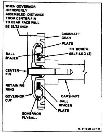
a. Remove (see figure 7-24). On ASK equipped generators, refer
to Operator and Organizational Maintenance Manual and remove
cover assembly. Remove retaining ring from camshaft center pin and
slide cup off. Be sure to catch the ten flyballs that will fall out when
cup is removed.
b. Repair. Replace any flyballs that have flat spots
or grooves. Replace cup if race surface is grooved
or rough. The governor cup must be a free spinning
fit on camshaft center pin, but should be replaced if
excessively loose or wobbly. Check distance the
center pin extends from the camshaft gear, this dis-
tance must be 25/32 inch to give proper travel dis-
tance for the cup (see figure 7-24). If it is less, the
engine may race; if more, the cup will not hold the
balls properly. If distance is too great, drive or
press center pin in. If it is too small, replace pin; it
cannot be removed without damaging the surface. If
aluminum ball spacer openings are badly worn, re-
place ball spacer. Remove self-locking flat head
screws, install new screws, ball spacer and plate.
c. Install. To install governor assembly, fill flyball recesses with
grease MIL-G-23827 and install flyballs. Position governor cup on
shaft and install retaining ring. On ASK equipped generators, refer to
Operator and Organizational Maintenance Manual and replace ASK
cover assembly.
7-16. CAMSHAFT ASSEMBLY AND TAPPETS.
a. Removal.
(1) Refer
to Operator and Organizational
Maintenance Manual and remove blower housing.
(2) Refer to paragraph 2-9 and remove engine.
(3) Refer
to Operator and Organizational
Maintenance Manual and remove rocker arm covers.
TM5-6115-585-34
NAVFAC P-8-623-34
TO-35C2-3-455-2
TM-05684C/05685B-34
Figure 7-24. Governor Cup Assembly
(4) Refer to paragraph 7-14 and remove gear
cover.
(5) Refer to paragraph 7-18 and remove fuel in-
jection pump.
(6) Remove crankshaft gear retaining washer (9,
figure 7-21) by removing lock ring (8) on the crank-
shaft.
(7) Refer to paragraph 7-9 and remove rocker
arms and push rods.
(8) Refer to paragraph 7-10 and remove oil base.
(9) Lay engine on side to avoid dropping tappets
(28) and remove camshaft assembly (15) as a group.
If necessary, pry it out with a screwdriver between
camshaft gear and crankcase. Remove retaining ring
(16) and press gear (17) off camshaft.
(10) Remove the valve tappets (28). These can be
removed only from bottom of crankcase.
(11) Refer to paragraph 7-17 and remove crank-
shaft gear.
Change 6
7-25