TM5-6115-585-34
NAVFAC P-8-262-12
TO-35C2-3-455-2
TM-05684C-34
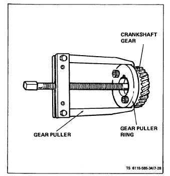
Figure 7-28. Crankshaft Gear Removal
(14) Remove center main bearing housing (29)
and center bearings (31 and 32) and remove crank-
shaft (33) through rear opening in crankcase.
b. Clean and Inspect.
(1) Crankshaft. Clean crankshaft and blowout all
oil passages. Check journals for out-of-round, taper,
grooving or ridges. Pay particular attention to ridges
or grooves on either side of oil hole areas. Unusual
conditions here often point to previous neglect of oil
changes. If journal dimensions are not within limits
or journals are scored, metallize and regrind crank-
shaft to standards.
(2) Bearings. Replace bearings if clearances are
greater than limits (see table 1-2), or if bearings are
worn, grooved or broken.
(3) Rear Oil Seal. Inspect seal for wear or dam-
age which might cause it to leak.
c. Rebuild Crankshaft. If crankshaft requires re-
grinding, metallize and regrind to standards. Special
procedures must be observed when reworking diesel
crankshafts. In addition to regrinding, the crankshaft
must be shot -peened and super-finished. Failure to
shot-peen the crankpin fillets is likely to cause early
failure. When the shaft is reground, follow this data
and figure 7-29 to shot-peen each crankpin fillet.
(1) Almen gauge reading, 0.012-A.
(2) Peen with 0.019 inch diameter cast steel shot.
(3) Peen for 30-seconds on each crankpin fillet.
7-28
Figure 7-29. Crankshaft Peening
(4) Mask off connecting rod bearing areas.
d. Installation.
NOTE
After each installation step, check crankshaft
to be sure it is not frozen in place.
(1) Heat cylinder block (34, figure 7-15) and bear-
ing plate (19) at 325° F (163° C) in an oven 30 minutes
and press front and rear main bearings (22) into place,
aligning bearing housing oil holes (see figure 7-30).
(2) Install thrust washers (25, figure 7-15) on
locking pins (see figure 7-30).
(3) Oil bearing surfaces and install crankshaft
(33, figure 7-15) from rear of crankcase, through
rear bearing plate hole.
(4) Set the upper half of the center main housing
(29) on the crankshaft (33) and rotate it into place. Be
sure it is installed with the side marked f rent toward
the crankshaft gear. Set the two positioning dowels
(30) on the upper bearing mount. Install the center
main bearing cap (29) and torque the bolts (27) to 97-
102 ft-lbs.
(5) Place gasket (23) on each side of shim (24).
(6) Before installing bearing plate, tape keyway
and sharp edges on crankshaft to protect the oil seal