TM5-6115-585-34
NAVFAC P-8-262-12
TO-35C2-3-455-2
TM-05684C-34
Table 7-1. Button Code Letter and Size
Code
No.
Or
Letter
16
15
14
13
12
1
2
3
4
5
s
R
P
N
M
A
B
c
D
E
Part No.
147A186
147A187
147A188
147A189
147A190
147A147
147A148
147A149
147A150
147A151
Size
0.134
0.131
0.128
0.125
0.122
0.119
0.116
0.113
0.110
0.107
(b) Remove delivery valve cap nut and delivery
valve holder (figure 7-43). A 12 point socket or box
wrench must be used on delivery valve holder to keep
from damaging this part. Lift out delivery valve spring
only, and leave it out, replacing delivery valve holder,
and delivery valve cap nut and gasket.
(c) Turn blower wheel clockwise until Number
1 cylinder (closest to blower wheel) is on compression
stroke, which follows closing of intake valve.
(d) Set throttle lever on injection pump to wide
open or up position (compress stop solenoid plunger
spring or remove stop solenoid assembly). Connect
Number 1 cylinder fuel line to Number 1 pump outlet
so that fuel line projects from the engine, hanging
down. Position receptacle for fuel under the line. Con-
nect lines from fuel supply to transfer pumps, trans -
fer pumps to filter, and filter to injection pump,
operate fuel transfer pumps to obtain fuel pressure
at injection pump. This can be done on the unit by
turning master switch to PRIME & RUN, or just by
applying 24 volts dc across the transfer pump. Ro-
tate blower wheel about one inch counterclockwise so
that P.C. mark is below timing pointer hole.
(e) Rotate blower wheel clockwise until fuel
flows from Number 1 cylinder fuel line. Continue
rotating slowly clockwise until fuel stops flowing. The
point at which fuel stops flowing from Number 1 cyl-
inder fuel delivery line is the injection pump port
closing point. Stop rotation of engine at exactly the
port closing point (l-2 drops in 5-10 seconds).
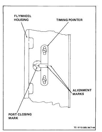
(f) Check timing pointer in the timing port on
the side of the generator adapter (figure 7-44). If
7-40
Figure 7-44. Timing Port and Port Closing Mark
timing pointer coincides with the P.C. mark stamped
on flywheel, the injection pump button thickness is
correct. If the P.C. mark on flywheel is below the
pointer, injection pump is closing early, and will re-
quire a thinner button. If the P.C. mark on flywheel
is above the pointer, injection pump is closing late
and will require a thicker button. Each mark on fly-
wheel indicates a difference of 0.006 inch button
thickness or 2 steps in button code number. (Example:
The P.C. mark on flywheel is above pointer. The
pointer indicates 1-1/ 2 marks difference. A button
0.009 inch thicker or 3 steps difference in button
number code is indicated. Since a Number 12 or M
button is installed, a letter R button is needed. )
(g) Remove injection pump and insert proper
timing button, taking the same precautions not to lift
the assembly containing face gear, when removing
timing button.
(h) Repeat injection pump installation.
(i) Check injection port closing point by re-
peating steps three through six. The timing pointer
should indicate the P.C. mark on flywheel. In no case
should pointer be more than 1/2 mark away from the
P.C. mark.
(j) Install delivery valve components. Be sure
ll parts are clean, and assembled carefully and