TM 5-6115-584-12
NAVFAC P-8-622-12
TO-35C2-3-456-1
TM-05682C-12
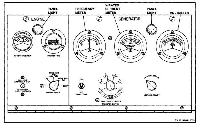
Figure 2-3. Starting Procedure
pushing speed control knob in will decrease frequency.Text
h. Place ammenter-volmeter transfer switch in
For fine-control turn knob CW to increase and CCW
to decrease.
f. Place ammeter-voltmeter transfer switch in
position corresponding to the position of the recon-
nection switch. Adjust voltage adjust rheostat to de-
sired voltage as read on voltmeter. Turn rheostat
clockwise to increase voltage or counterclockwise to
decrease voltage.
g. Place AC circuit breaker in ON position. Adjust
speed control to obtain 60 Hz.
position to check percent rated current for either
1-phase 120 V. output, 1-phase 120/240V. output, or
3-phase 120/208 V. output. See table 2-1 and figure
2-3.
NOTE
For 3-phase output each of the four positions
indicated in table 2-2 must be checked.
Observe percent rated current meter. Do not exceed
5% load difference between phases. A 0.8 power factor
Table 2-2. Reconnection Switch Positions
Load Voltage and Phase
120V 1 phase
120/240V 1 phase
120/206V 3 phase
Switch Position
Amps - Volts - Phase
L3
L3-L1
1
L3
L3-L0
1
L1
L1-L2
3
L2
L2-L3
3
L3
L3-L1
3
L3
L3-L0
3
Measurement Across Terminals
L3-L1
L3-L0
L1-L2
L2-L3
L3-L1
L3-L0
2-4