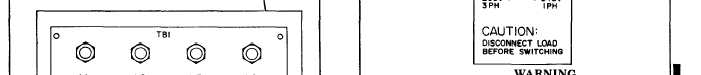
Figure 2-1.. Load Terminals
Figure 2-1.
Figure 2-2.
TM 5-6115-584-12
NAVFAC P-8-622-12
TO-35C2-3-456-1
TM-05682C-12
Table 2-1. Generator Set Controls and Instruments (Cont)
Control
Description
Function
OIL PRESSURE
Located on oil fill side of engine.
Indicates engine oil pressure.
GAUGE
0-50 pounds per square inch (psi)
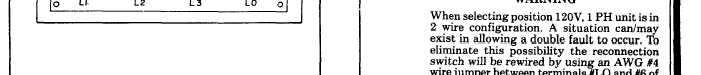
RECONNECTION
Located on output control box.
Used to select 120V, 1 phase; 120/240V, 1 phase; or
SWITCH
Three position rotary switch.
120/208V, 3 phase output for Generator Set.
c. Place master switch in START position and
hold until engine comes to operating speed. If engine
does not start within 15 seconds repeat steps b and c.
NOTE
If engine does not come to operating speed
within 15 seconds, a minimum of 30
seconds cooling period must be observed
before attempting another start.
d. Master switch will return to PRIME & RUN
position when released. If running from auxiliary fuel
source, move master switch to PRIME & RUN AUX.
FUEL position.
e. Check oil pressure on engine mounted gauge. Oil
pressure should be at least 20 psi minimum. Check
frequency on frequency meter on control panel and
adjust governor if necessary, using speed control.
Frequency meter should read 61.5 with no load. Pull-
ing speed control knob out will increase frequency,
Change 6
2-3