TM 5-6115-584-12
NAVFAC P-8-622-12
TO-35C2-3-456-1
TM-05682C-12
plug is clean and tight. Check for leakage where the
glow plug enters cylinder head.
b. Test. Remove electrical lead to glow plug. Use
ohmmeter to test for continuity. from terminal of
glow plug and ground, Open circuit indicates bad glow
plug.
With master switch in the PREHEAT position,
24 volts dc is applied to the glow plug body. Do
not handle plug with the master switch in the
PREHEAT position.
c. Remove. Disconnect lead to glow plug. Unscrew
glow plug and remove it from cylinder head. If glow
plug was leaking where it entered cylinder head, re-
move gasket with a hooked wire and replace.
d. Install, If gasket (2, figure 4-42) has been removed, place
new gasket over glow plug. Coat plug threads with anti-seize
compound and screw glow plug into cylinder head. Tighten glow
plug 10 to 15 ft-lb dry. Attach electrical lead to plug. On ASK
equipped generators, install top panel assembly (para. 5-4).
4-49. OIL DRAIN HOSE VALVE.
a. Replace (see figure 3-20). On ASK equipped gener-
ators, remove oil access door, Drain engine 011 Into a suitable
container. Disconnect oil drain hose from valve. Remove
valve. Attach serviceable hose to valve. Use pipe thread
sealant on allpipe threads, Always store hose against frame
when not in use.
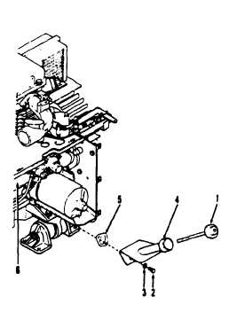
1. Oil level indicator
4 . O i l f i l l
2. Screw (2)
5. Gasket
•3. Lockwasher (2)
6. Cylinder block
TS 6115-584-12/4-43
4-50. OIL BASE.
Figure 4-43. Oil Fill Tube
a. Inspect. Inspect oil base for dents, cracks, or
other physical damage. Check for leaks, especially at
the gasket between oil base and cylinder block.
4-51. OIL PILL TUBE.
a. Remove (see figure 4-43). On ASK equipped gener-
ators, remove oil access door. Remove oil level indicator (1).
Remove screw (2), and Iockwasher (3). Remove oil fill tube
(4) and scrape gasket (5) from mating surface on cylinder
block (6) and oil fill tube (4).
b. Installation. Install gasket (5) between oil fill
tube (4) and cylinder block (6). Attach oil fill tube (4)
with screw (2) and lockwasher (3). Install oil level
indicator (1) in oil fill tube (4).
4-52. ENGINE MOUNTING ASSEMBLY.
a. Inspect (see figure 4-44). On ASK equipped gener-
ators, remove cover assembly. (para 5-3). Check to see that
mounting nuts and bolts are tight. Cheek rubber mounts (14)
for cracks and breaks.
(1), lockwasher
(3), flatwasher (2) and nuts (4) that
secure each mounting assembly to skid-base (5). Re-
move screws (6), lockwashers (7) and flatwashers (8)
and remove mounts.
c. Disassembly. Remove screw (9), nut (10), lock-
washer (11) and flatwasher (12). Remove brackets
(13). Remove resilient mounts (14) and spacer (16)
from bracket (17). Do not remove alignment pin (15),
unless it is damaged.
d. Reassembly. Install mounts (14) and spacer (16)
into bracket (17). Using screw (9), flatwasher (12),
lockwasher (11) and nut (10), assemble brackets (13)
to the mount.
e. Installation. Install mounts on engine and secure with screw
(6), Iockwasher (7) and flatwasher (8). Lower engine and mounts
to skid-base and secure mounts to base with screws (1), washers
b. Remove. Use engine lifting assembly to remove
weight off of mounting assembly and remove screws
4-54
Change 7
(2), Iockwashers (3) and nuts (4). On ASK equipped generators,
install ASK cover assembly (para 5-3).


