TM 5-6115-584-12
NAVFAC P-8-622-12
TO-35C2-3-456-1
TM-05682C-12
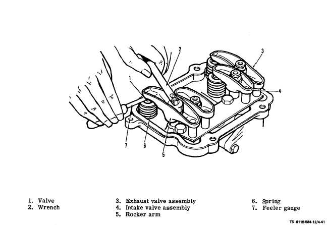
Figure 4-41. Checking and Adjusting Rocker Arm to Valve Clearance
Always check and adjust the valve tappet clearance
head. Correct valve clearance is 0.010 for intake
when the engine is at an ambient of approximately
70°F (18°C). Remove rocker cover and proceed as
follows :
Turn blower wheel clockwise only.
(1) Using 5/8" socket wrench and extension, turn
the blower wheel clockwise until No. 1 cylinder is on
its compression stroke, which follows the closing of
its intake valve. See figure 4-41 for identification of
intake valve assembly.
(2) Continue clockwise rotation until the letter
“A” appears in the timing port on the side of the
generator adapter. This puts No. 1 cylinder in the
power stroke with both valves closed.
(3) By using a feeler gauge, check the clearance
between the rocker arm and the valve stem cap. See
figure 4-41. Increase or reduce the clearance until
the proper gap is established, adjusting with the lock-
nut which secures the rocker arm to the cylinder
4-52
valve, 0.007 for exhaust valve.
(4) To adjust the valve clearance for No. 2 cyl-
inder, turn the blower wheel clockwise 180° until the
letter “B“ appears in the timing port and adjust valves
as given in step 3.
(5) Install rocker cover and tighten screws 7 to
8 ft-lb.
4-47. INJECTOR NOZZLE ASSEMBLY AND FUEL
LINES.
a. Inspect.
(1) Injector Nozzle Assembly (see figure 4-42).
Inspect for leaking fuel. Inspect fuel fittings for tight-
ness.
(2) Fuel Lines. Inspect fuel lines for leaks and
damage to fittings.
4-48. GLOW PLUG ASSEMBLIES.
a. Inspect (see figure 4-42). Inspect glow plugs for
physical damage. Check that electrical lead to glow