4-43. INTAKE MANIFOLD A S SEMBLY.
a. Test On Equipment (see figure 4-36). On ASK equipped
generators, remove right panel assembly (para. 5-6). Remove hose
between intake manifold and air cleaner to permit visual inspection
of heater coils (18). Place master switch (see figure 2-3) in the
PREHEAT position. Good coils should start to heat within one
minute. Release switch as soon as coil begins to heat. Replace a
bed heater.
b. Inspect. Inspect heater for physical damage.
Check that electrical connections to heater are clean
TM 5-6115-584-12
NAVIFAC P-8-622-12
TO-35C2-3-456-1
TM-05682C-12
and tight. While engine is operating, check for leaks
especially at the gasket (15; figure 4-36) between
manifold and cylinder head and the gasket (25) between
the manifold heater adapter (24) and the manifold.
Drop oil from an oil can or hold piece of thin paper
on point suspected of leaking. If leak exists, oil will
be sucked in or paper will be sucked against leaking
area.
c. Remove. Tag and disconnect leads (17 and 19)
from heaters (18) and remove heaters (18). Remove
lead (19) by removing screw (20), washers (21 and
22) and spacer (23). Remove adapter (24) and gasket
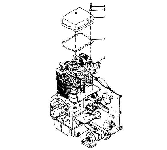
1. Screw (4)
2. Lockwasher (4)
3. Rocker arm cover
4. Gasket
5. Cylinder head
TS 6115-584-12/4-38
Figure 4-38. Rocker Arm Covers
Change 7
4-49