TM 5.6115-584-12
NAVFAC P-8-622-12
TO-35C2-3-456-1
TM-05682C-12
4-37. LOAD TERMINAL BOARD ASSEMBLY.
a. Load Terminal Removal (see figure 4-32).
(1) Unlatch door (3).
(2) Remove screws (1), lockwasher (2), and cover
and door assembly (3).
(3) Remove screws (4) and lockwashers (5).
(4) Carefully lift terminal board (6) and tag and
disconnect leads from load terminals (7) by removing
nut (11 ), lockwasher (10) and flatwasher (9).
(5) Remove load terminal (7) from terminal board (6)
by removing nut (8), flatwasher (12) and lockwasher (13).
b. Load Terminal Installation (see figure 4-32).
(1) Install load terminal (7) to terminal board (6)
by installing lockwasher (13), flatwasher (12) and nut (8).
(2) Connect leads to terminals (7) by installing
flatwashers (9), lockwashers (10) and nut ( 11).
(3) Install lockwashers (5) and screws (4).
(4) Install door assembly (3), lockwashers (2) and
screws (1).
(5) Latch door.
c. Replacement of Lost or Broken Terminal Clip
(Retainer Safety Clip), The terminal clip is a component of
both the load terminal and the ground terminal. If the ter-
minal clip is lost or broken, fabricate as follows:
(1) Requisition bulk wire NSN 9505-00-804-3814
(0.042 inch diameter) for the ground terminal (ground
stud). Requisition bulk wire NSN 9505-01-049-0144 (0.050
inch diameter) for the load terminal.
(2) Cut off about 3 inches of the wire, short enough
to keep the clips from touching another terminal or the
generator frame in the open or closed position,
(3) Slip the wire through the hole in the terminal.
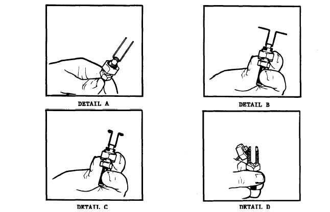
(4) Hold the terminal as shown (Detail A, figure
4-32.1) and bend both ends of the wire straight up keeping
the wire in as straight a line as you can with terminal body.
(5) Bend the wire into back-to-back 90° angles
(Detail B, figure 4-32.1) so that the legs of both angles are
about one-half inch long.
(6) Bend the ends of each 90° angle down and
around into a U-shape (Detail C, figure 4-32.1) so that if
done properly, the clip will hold the nut when it is un-
screwed to install the cable (Detail D, figure 4-32.1).
Figure 4-32.1. Terminal Clip Replacement
4-40
Change 5


