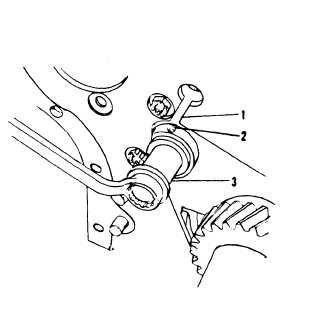
1. Slot
2. Oil hole
3. Idler gear shaft
ME 6115-545-34/14-35
Figure 14-35. Idler Gear Shaft Installation
(3) If idler gear shaft is scored or worn it
must be replaced The specified outer diameter on
both ends of the idler gear shaft is 0.999”-1.000”.
Install a 9/16 -18 adapter in the end of the idler
gear shaft. Install the end of the slide hammer into
the adapter and remove the idler gear shaft from the
cylinder block.
d. Camshaft Gear Removal. Refer to para-
graph 14-77 for removaI procedures.
e.
Crankshaft Gear Removal. Use bar type
puller and remove crankshaft gear.
f .
Hydraulic Gear Removal. (Class 1 sets
only (para 14-14)
14-73. Timing Gears and Housing Cleaning and In-
spection.
Clean cover and gears using cleaning sol-
vent, Federal Specification P- D-680.
b. Clean all gasket material from timing gear
cover using care to prevent scoring or gouging of
surface.
c. Inspect front support plate for damage and
wear.
d. Inspect idler gear shaft for scoring or
wear The center diameter on both ends must be
0.999 to 1,000 inch.
e.
Inspect all gears for excessive wear and
chipped or broken gear teeth
14-74. Timing Gears and Housing Repair.
a.
Repair is limited to replacement of
housing, front support
worn or damaged.
b. Replace idler
excessively worn beyond
to step d. above.
14-75. Installation.
plate, or gears if badly
gear shaft if scored or ex-
the allowable limits. Refer
a.
Crankshaft Gear Installation
—
(1) Install woodruff key in crankshaft.
(2) Heat gear in oil to a temperature of
approximately 300° F.
(3)
a mixture of
(4)
Coat crankshaft at gear location with
white lead and oil.
Drive or press gear onto crankshaft.
CAUTION
Use asbestos gloves when handling
the heated gear.
(5) When crankshaft is installed in engine
make certain that timing mark a crankshaft gear
is aligned with timing mark, on camshaft gear when
crankshaft gear is installed.
b. Camshaft Gear Installation. See figure
14-35 and proceed as follows:
(1) Insert idler gear shaft into cylinder.
Block bore so that oil hole on top of shaft aligns
with slot in front plate.
gear
until
(2) Insert washer and capscrew into idler
shaft (see fig. 14-34) and tighten capscrew
shaft bottoms in cylinder block
NOTE
The bore size of the roller bearing
is 1.000-1.008 inches and the
outer diameter of the outer race of
the bearing is 1.980-1.981 inches.
The bore size of the idler gear is
1.9785-1.9795 inches and the bore
size of the groove in the idler gear
for the spacer is 2.068-2.078
inches. If the bearing assembly is
worn, drive the outer races out with
a punch and press in the new races
until they contact the newly installed
spacer.
14-74