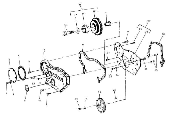
1.
screw
2.
Washer
3. Cover
4.
Gasket
5.
Screw
6. Screw
7.
Screw
8. Screw
9.
10.
11.
12.
13.
14.
15.
16.
Screw
Screw
Oil seal
Pointer
Cove r
Gasket
Screw
Gear assy
17.
Washer
24.
18.
G e a r c l u s t e r 2 5.
19.
Bearing
26.
20.
Screw
27.
21.
washer
28.
22.
cam shaft
29.
gear
30.
23. key
31.
Bolt
Screw
washer
Plate assy
Plate
stud
Gasket
Shaft
Figure 14-34.
Timing Gear and Cover
ME 6115-545-34/14-34 C6
(2) Remove nut and lockwasher securing gear
to fuel pump drive shaft.
(3) Remove the fuel injection pump, from the
fuel pump drive shaft (para 14-43).
(4) Remove the two oil seals from the fuel
pump drive shaft.
Inspect oil seals for wear or
damage. Replace if necessary.
(5) Withdraw the fuel Pump drive shaft, with
the drive gear attached, from the mounting adapter
and through the opening in the timing gear cover.
(6) Position fuel pump drive shaft and drive
gear on a press and remove the fuel pump drive
gear from the drive shaft. Inspect drive gear and
replace if necessary.
c. Idler Gear Removal. See figures 14-34 and
14-35 and premed
as follows:
(1) Remove capscrews and washer securing
idler gear.
(fig. 14-34)
(2) Remove idler gear with bearings.
Change 6
14-73