coil.
This can result in questionable
operation and rejection of good coils
under some conditions. Do not attempt
to check solenoid operation with the
cover removed from the pump. The
governor linkage spring aids operation
when the cover is assembled.
g. Reassemble solenoid.
ME 6115-545-34/14-22
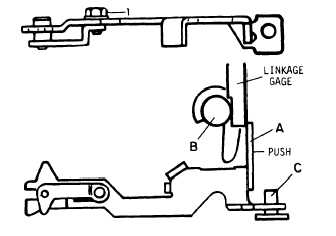
Figure 14-22.
ThrottIe Linkage Adjustment
of the contact screws. Check the solenoid for a com-
plete circuit with an ohmmeter.
e. Assemble the shut-off arm (15) and spring (13)
and guide (14) to the coil. Before installation of the
solenoid assembly to the cover is made, adjustment of
the arm travel and spring tension should be carried
out as illustrated in figure 14-23. Install new insulating
tubes (11, 12) to both contact screws. Insert the assem-
bly into the governor control cover as a unit. Replace
the insulating washer (10) and assemble the contact
nuts (7,8) (20-25 inch-pounds). Mount the cover assem-
bly, with new cover seal (6), to the pump and tighten
securely.
f. With the pump mounted on the test bench, the
electrical shut-off device must be checked with 24 Vdc
and wide open throttle at the following speeds:
(1) 400 rpm
(2) Full load governed speed
(3) High idle (shut-off only)
NOTE
If use of automotive type batteries is im-
practical, a good, heavy duty battery
charger can be used as long as voltage can
be selected and will hold with minimum
drop (1/2 volt max. ) during application to
the solenoid coil.
Use of small, inexpen-
sive trickle chargers is not recommended,
since a voltage drop of 2-3 volts can be
expected when current is applied to the
h. Install solenoid on fuel injection pump.
—
i. On equipment test.
Energize solenoid with
24 Vdc. If a clicking sound is heard, then the sole-
noid is operating.
14-47. Variable Speed Droop Device.
a. Remove the cover, shut-off cam, shut-off
shaft assembly, throttle shaft assembly, throttle
shaft lever, and governor linkage hook. Remove end
plate assembly.
b. Remove the adjusting cap (8, fig. 14-24) by
pulling to the rear of the pump. With a pair of needle-
nose pliers, remove the control rod clip (4). Do not
bend the control rod. Loosen and remove the control
rod guide (6), “O” ring (5) and guide washer (1 5).
Disengage the governor spring (2) from the governor
arm (1) and remove the governor spring and control
rod assembly as a unit.
c. Examine the governor spring for distortion and
the–spring guide and bushing for excessive wear.
Replace the two seals on the control rod guide.
Check control rod for straightness and replace, if
needed.
d. Insert the control rod assembly (3) through the
threaded hole from the inside of the housing. Slide
the control rod guide (6), O ring (5) and guide (9) over
the end of the control rod (3), and thread into hous-
ing. Tighten securely. Insert clip (4) into the con-
trol rod end being careful not to bend the rod. Slide
the adjusting cap (8) over the new seal on guide (6).
Thread five full turns of governor spring (2) onto the
spring guide (9) with the spring guide and bushing (10)
against each other as shown in figure 14-24. Slip the
free end of the governor spring over the formed ends
of the governor arm (1) with the bent end of spring
between the two tabs.
e. Install the end plate, throttle shaft assembly,
throttle shaft lever, shut-off shaft assembly, and
shut-off cam. Adjust low idle adjusting screw so
bushing (10) just touches rod guide and forked end of
throttle shaft lever straddles and engages flats on
bushing. Replace cover.
The speed droop assembly
is now positioned for minimum droop.
f. During bench test, make normal check of out-
put, metering and transfer pump pressure at full load
governed speed as called for in paragraph 14-48. High
idle adjusting screw should be backed all the way out
and throttle held open as far as possible. Refer to par-
agraph 14-48 for bench test of fuel injection pump. See
figure 14-24 while making adjustments an speed droop.
14-51