REF DES
Re
M2, M3
Vl
V2
TEST EQUIPMENT
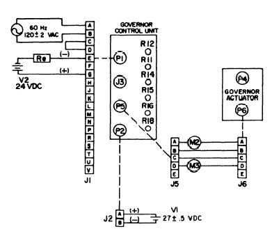
PARALLEL WINDING TEST
CONNECT GOVERNOR CONTROL
UNIT TO TEST EQUIPMENT AS
SHOWN.
M2 SHALL READ 0-300 MA.
M3 SHALL READ 600-840 MA.
REVERSE POLARITY OF CONNECT-
IONS TO PINS J1-E AND J1-G.
M2 SHALL READ 600-840 MA.
M3 SHALL READ 0-300 MA.
QUANTITY
DESCRIPTION
1
RESISTOR, FIXED, 50,000 OHMS, 10 WATT
2
MILLIAMMETER, DC, 0-1000 MA
1
DC POWER SOURCE
1
DC POWER SOURCE
1
AC POWER SOURCE
ME 6115-545-34/7-6
Figure 7-6. Electric Governor Control Unit Parallel Winding Test (50/60 Hz)
(7) The adjustment of R18 and R16 are
interdependent.
For any position of R18 there is an
optimum position for R16. Therefore, to improve
transient performance, increase the frequent y gain
by turning R18 clokwise.
If hunt develops, readjust
R16 for stability. If no hunt develops, apply and
reject load on the generator set to check for stability
under transient conditions. Assuming that no hunt
develops for an increase in frequency gain, (R18
turned clockwise) or that hunt can be removed by
readjustment of R16, again increase frequency gain.
by turning R18 clockwise and note the transient per-
formance. Finally a position may be reached where
no readjustment of R16 can stabilize for the high
frequency gain of R18. Then reduce the frequency
gain to the stable region and optimize stability
and performance with R16. The frequency gain
should be reduced to a point where the system is
not on the edge of instability for long-term stable
operation.
(8) Transient performance improves as the
frequency gain R18 is increased and the feedback
gain R16 is a minimum for that particular position
of frequency gain adjustment. If R16 is adjusted
too far counterclockwise, there will be insufficient
feedback to stabilize the operation at steady state.
If a slow oscillation occurs, turn R16 clockwise until
stability is reached.
This is the optimum setting for
the level of frequency gain.
(9) If R16 is turned far clockwise, a very fast
oscillation may occur.
Turn R16 counterclockwise
to the optimum point of stability.
b. Parallel Operation (Class 1 sets)
(1) Adjust in accordance with paragraph 16-11.
(2) If the sets will not divide load, or if they
oscillate (successively interchange load) on the first
attempt to parallel, check the polarity across pin
A and B of the parallel receptacle on both sets and
verify, that the input circuits to pin C and D are
correct and that the voltages are as specified.
7-9. Equipment Test
If the electric governor control has been renewed or
repaired, refer to Chapter 16, Section II and conduct
the following tests.
a. Frequency and voltage regulation, stability and
transient response test, short term. (para 16-15)
b. Frequency adjustment range test (para 16-16)
Change 1 7-9