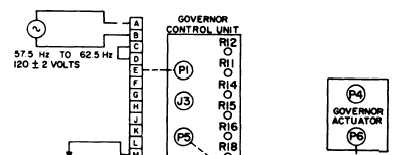
FREQUENCY SENSING CHECK (HIGH AND LOW
REF DES
Ra
Rb, RC
M2., M3
Vl
FREQUENCY)
CONNECT GOVERNOR CONTROL UNIT TO
TEST EQUIPMENT AS SHOWN
TURN Ra SO THE Resistance BETWEEN
P1-M AND Pl-T IS 250 OHMS.
REDUCE THE FREQUENCY OF THE AP-
PLIED 120 ± 2 VOLT SUPPLY UNTIL M2
AND M3 BALANCE.
THE FREQUENCY SHALL BE 57-58 Hz.
TURN Ra SO THE RESISTANCE BETWEEN
P1-M AND P1-N IS 250 OHMS.
INCREASE THE FREQUENCY OF THE AP-
PLIED 120 ± 2 VOLT SUPPLY UNTIL M2
AND M3 BALANCE.
THE FREQUENCY SHALL BE 64-65 Hz.
TEST EQUIPMENT
QUANTITY
DESCRIPTION
1
POTENTIOMETER, 10 TURN, 500 OHM, 5 WATT
2
RESISTOR, FIXED, 250 OHM, 5 WATT
2
MILLIAMMETER, DC, 0-1000 MA
DC POWER SOURCE
AC POWER SOURCE
ME 6115-545-34/7-4 C1
Figure 7-4. Electric Governor Control Unit, Frequency Sensing Check (High and
Low Frequency) (50/60 Hz)
e. Magnetic Amplifier Bias Test (50/60 Hz).
Refer to figure 7-3 and perform the magnetic ampli-
fier bias test.
f. Frequency Sensing Check, High and Low
Frquency (50/60 Hz). Refer to figure 7-4 and
perform the frequency sensing check.
g. Rectifier Bridge, CR7 thru CR30 and Feed-
back Winding Test (50/60 Hz). Refer to figure 7-5
and perform the rectifier bridge and feedback winding
test.
h. Parallel Winding Test (50/60 Hz). Refer to
figure 7-6 and perform the parallel winding test.
i. Resistance Test (400 Hz). Refer to Table 7-3
and perform resistance test.
j. Magnetic Amplifier Bias Test (400 Hz). Refer
to figure 7-7 and perform the magnetic amplifier bias
test.
k. Frequency Sensing Check, High and Low
Frequency (400 Hz). Refer to figure 7-8 and per-
form the frequency sensing check.
L Rectifier Bridge, CR7 thru CRl0 and Feed-
back Winding Test (400 Hz). Refer to figure 7-9
7-6 Change 1
and perform the rectifier bridge and feedback
winding test.
m. Parallel Winding Test (400 Hz). Refer to
figure 7-10 and perform the parallel winding test.
n. Replace any component found to be defective
during tests.
o. For wiring harness repairs, refer to Operator
and organizational Maintenance Manual.
p. If wiring harness has sustained extensive
damage, refer to Chapter 5 for wiring harness
rebuilding procedures.
7-7. Assembly.
a. See figure 7-12 and assemble printed circuit
board. If any connections are opened or bared for
test purposes, or if any defective components are
replaced, the effected area and components must be
coated with polyurethane resin to prevent oxidation
or other corrosion .
The coating must be of a min-
imum thickness of 0.007 inches and air bubble entry
into the applied polyurethane must be controlled so
that the legibility of component coding and identifi-
cation is not impaired. The polyurethane resin to
be utilized will correspond to MIL-I-46058,