REF DES
QUANTITY
TEST EQUIPMENT
DESCRIPTION
Rd
1
RESISTOR, FIXED, 5000 OHMS, 1 WATT
Rf, Rg
2
RESISTOR] FIXED, B2 OHM, 10 WATT
Rh, Ri
2
RESISTOR FIXED, 15 OHMS, 5 WATT
Rj
1
RESISTOR, FIXED, 25 OHMS, 5 WATT
M2, M3
2
MILLIAMMETER, DC, 0-1000 MA
M4
1
MILLIAMMETER, DC, ZERO CENTER,
10-0-10 MA
1
SWITCH, ROTARY, 3 POSITION, 1 POLE, 1 AMP
1
DC POWER SOURCE
1
AC POWER SOURCE
1
AUTOTRANSFORMER 2:1 RATIO
ME 6115-545-34/7-5
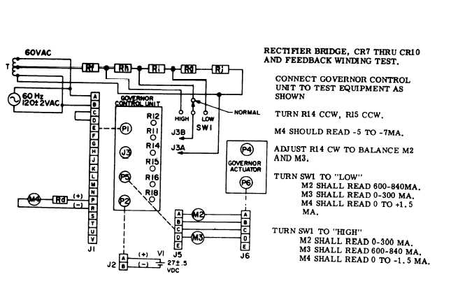
Figure 7-5. Electric Governor Control Unit, Rectifier Bridge and Feedback Winding Test
(50/60 Hz)
(3) Once the set has been stabilized, connect
a 0 - 10 volt range dc voltmeter (high impedance
type -2000 ohms per volt or more) across test
points 3 and 4 with the positive lead at test point 4.
Adjust FREQUENCY ADJUST control to obtain oper-
ating frequency (400 W, or 60 Hz), and then adjust
R14 until volt e across test points 3 and 4 is zero
volts, with no load on generator.
(4) Connect dc voltmeter across tests points 1
and 2 with positive lead at test point 1. Adjust R11
and the frequency adjust control until the dc volt-
meter reads zero volts at nominal frequency. Repeat
the adjustment until the voltage across test points 3
and 4 and across 1 and 2 is zero volts, and the set
frequency is 50 Hz, 60 Hz or 400 Hz with no load
on the engine. If test points 1 and 2 cannot be
zeroed, they must be reduced to a minimum.
(5) Adjust RI 2 until a reading of approximately
4.5 volts is obtained across test points A and B, with
no load on generator.
If this voltage is too low,
response will be sluggish and if it is too high, a rapid
oscillation may occur.
Normal range is 3 to 6 volts.
(6) Adjust R18 clockwise as far as possible,
and R16 counterclockwise as far as possible without
causing oscillation,
NOTE
Increasing the load measurement gain
R15 (turing in a clockwise direction)
will improve transient performance;
therefore it should be adjusted as high
as possible. Transient performance must
be checked using a frequency recorder.
7-8 Change 1