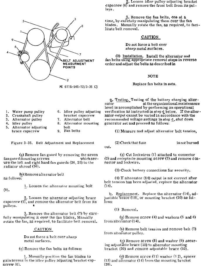
Figure 3-35.
(~) Remove fan guard by removing the seven
fan guard mounting screws ( 2 4 , f i g . 3 - 2 9 ) , which sec-
ure the left and right hand fan guards (26, 25) to the
radiator shroud (36).
(~) Remove alternator belt ( 7 , f i g . 3 - 3 5 )
as follows:
~. Loosen the alternator mounting bolt
(8).
2. Loosen the alternator adjusting brace
capscrew (5L and remove the alternator belt from its
pulleys.
@
3. Remove the alternator belt (7) by care-
fully manipu~ating it over the fan blades, Manually
rotate the fan, as required, to facilitate belt removal.
CAUTION
—
Do not force a belt over sharp
metal surfaces.
(~) Remove the fan belts as follows:
1. Manually position the fan blades to
gain access~o the idler pulley adjusling bracket cap-
screw (6).
2. Loosen idler pulley adjusting bracket
capscrew (6~and remove the front belt from its pul-
leys.
3. Remove the fan belts, one at a
time, by ca~efully manipulating them over the fan
blades.
Manually rotate the fan, as required, to faci-
litate belt removal.
CAUTION
Do not force a belt over
sharp metal surfaces.
(2)
Installation.
Install the alternator and
fan belts using appropriate removal steps in reverse
order and adjust the belts as described in
p a r a g r a p h
3 - 1 8 3 a ( 1 ) a n d ( 2 ) .
NOTE
Replace fan belts in sets.
3 - 1 8 4 .
B a t t e r y
C h a r g i n g
A l t e r n a t o r .
a. Testing. Testing of the battery charging alter-
nat;r ( 1 4 , f i g . 3 - 3 6 ) at the organizational maintenance
level is accomplished by performing an operational
verification as instructed in step c below.
If the alter-
nator output cannot be varied in a~cordance with the
recommended voltage settings in step ~, shut down
generator set and proceed as follows:
(1) Measure and adjust alternator belt tension,
( p a r a 3 - 1 8 3 a ( 1 ) a n d ( 2 ) .
(2) Check that fuse ( 2 1 , f i g . 3 - 3 6 ) is not burned
out ,
(~) Cut lockwires (1) attached to connector
(2) and receptacle mounting screw (3) and remove con-
nector and lockwire.
(3) Check battery connections for security.
(4) If alternator (14) output is not correct after
belt tension has been adjusted, replace the alternator
(14).
b.
Replacement.
Replace the alternator (14), ad-
jus~able brace (10), or mounting bracket (20) as fol-
lows:
(1)
Removal.
(a) Remove screw (4) and washers (5 and 6)
from alte~nator (1 4).
(b) Remove belt tension and remove belt (7)
from altei+nator pulley.
(c) Remove screw (8) and washer (9) secur-
ing adjust~ble brace (10) to alternator mounting
bracket (20) and remove adjustable brace (10).
(d) Remove screw (11) washer (1 2), spacer
(13) and afiernator (14) from the mounting bracket
(20).
C h a n g e
3
3 - 8 9